Manufacturing method of cooler

A manufacturing method and radiator technology, applied in heat exchange equipment and other directions, can solve the problems of unsatisfactory heat dissipation effect, long heat dissipation path of heat sink, short service life of heat source, etc., to achieve rapid conduction and dissipation, shorten heat dissipation path, and prolong use. effect of life

Inactive Publication Date: 2016-03-09
SIHUI HONGYI ELECTRONICS TECH CO LTD
View PDF5 Cites 2 Cited by
  • Summary
  • Abstract
  • Description
  • Claims
  • Application Information

AI Technical Summary

Problems solved by technology

Therefore, the radiator with this structure has problems such as long heat dissipation path and unsatisfactory heat dissipation effect, which leads to short service life of the heat source.

Method used


Image

  • Manufacturing method of cooler
  • Manufacturing method of cooler
  • Manufacturing method of cooler

Examples


Embodiment Construction

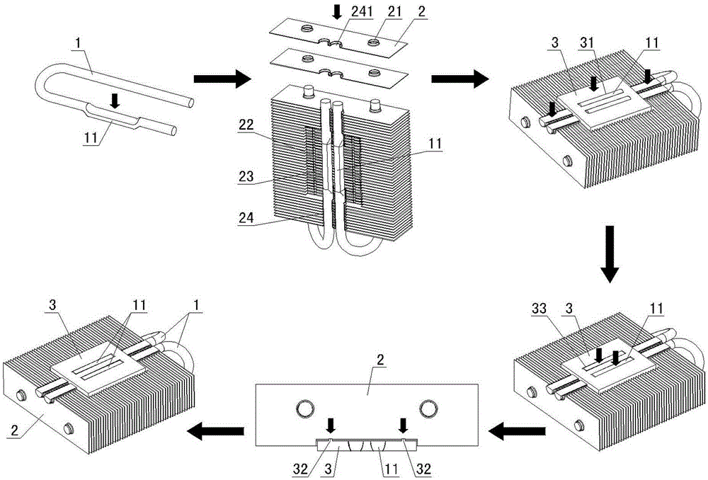
[0023] Such as Figure 1-Figure 3 Shown, the manufacturing method of radiator of the present invention, comprises the following steps:

[0024] Firstly, pre-press a pole of the U-shaped heat pipe 1 so that a boss 11 is formed on the pole;

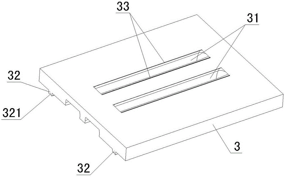
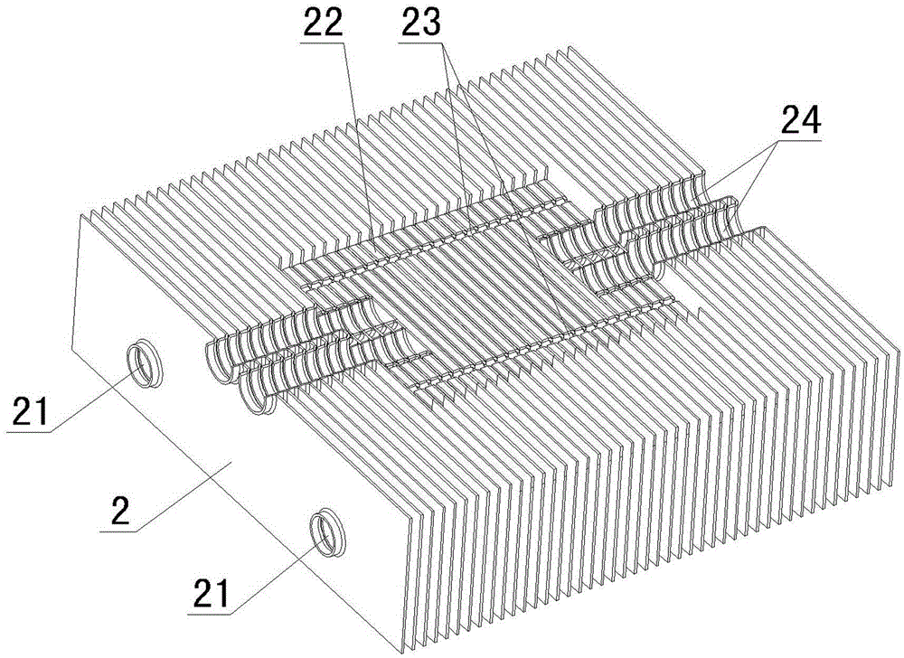
[0025] Then, the heat dissipation fins 2 are sleeved one by one on the other support rod of the U-shaped heat pipe 1 through the connecting holes 21 provided thereon, and are respectively fixed by riveting with the support rod, and each heat dissipation fin fixed by riveting is The fins 2 jointly form a heat dissipation fin group, and a groove 22 and a connecting groove 24 are formed on the surface of the heat dissipation fin group, and a snap groove 23 is formed in the groove 22, and the U-shaped heat pipe 1 is provided with a convex The pole of platform 11 is placed in connecting groove 24 and boss 11 is positioned at the position of groove 22; Wherein, as image 3 As shown, the groove 22 is a square groove, and the square groove is for...


PUM


Abstract

The invention provides a manufacturing method of a cooler. The method includes the steps that one strut of each U-shaped heat conductive pipe is pressed on a boss; cooling fins are riveted to the other strut of each U-shaped heat conductive pipe one by one; a bottom board and the boss are preliminarily riveted and fixed and meanwhile the two ends of each strut with the corresponding boss are riveted and fixed to the cooling fins; the boss is riveted, so that the boss is flush with the bottom board; and finally the bottom board and the cooling fins are riveted and fixed. The riveting process is adopted for manufacturing the cooler, no electroplating or welding process is needed, the process is simple, production efficiency is improved, production cost is reduced, energy is saved, and environmental friendliness is achieved. Meanwhile, the heat conductive pipes are flattened and then embedded in the bottom board, one side of each heat conductive pipe can make direct contact with a heat source, the other side of each heat conductive pipe makes direct contact with the cooling fins, heat resistance of an aluminum board is reduced, the heat conductive performance is effectively improved, a cooling path is shortened, heat generated by the heat source can be rapidly conducted and dissipated out, the cooling effect is improved, and the service life of the heat source is effectively prolonged.

Description

technical field [0001] The invention belongs to the technical field of radiators, and in particular relates to a method for manufacturing a radiator. Background technique [0002] A traditional heat sink is usually composed of a heat pipe, a bottom plate and cooling fins. However, since the heat pipes, bottom plate and heat dissipation fins that make up the traditional radiator are welded together by solder paste welding process, in order to meet the welding process requirements, some parts must be electroplated before welding, such as: bottom plate, heat dissipation fins Chips must be nickel plated before soldering. In this way, not only the process is complicated, the production efficiency is low, and the cost is high, but also high-energy-consuming processes such as electroplating and welding are required, which seriously damages the environment. At the same time, due to the heat dissipation through the heat sink of this structure, the heat generated by the heat source ...

Claims


Application Information

Patent Timeline
Patent Type & Authority Applications(China)
IPC IPC(8): B21D53/08B21D39/00
CPCB21D53/085B21D39/00
Inventor 张年松
Owner SIHUI HONGYI ELECTRONICS TECH CO LTD
Why Eureka
Try Eureka