A Method for Using Alloy Casting to Satisfy the Positioning of Complicated Shaped Workpieces

A technology for complex-shaped workpieces and alloys, which is applied in metal processing equipment, manufacturing tools, casting and molding equipment, etc., can solve problems such as unfavorable clamping, small blade body, and lack of clamping means for products, and achieve strong application space and solve assembly problems. The effect of clip positioning

Active Publication Date: 2017-05-10
SICHUAN CRRC YUCHAI ENGINE CO LTD
View PDF5 Cites 6 Cited by
  • Summary
  • Abstract
  • Description
  • Claims
  • Application Information

AI Technical Summary

Problems solved by technology

like figure 1 , 2 The turbine blade shown in the figure, the blade body is formed by precision casting, and the tenon needs to be ground on a powerful grinder. Because the blade body is small, it is not conducive to clamping, and there is a lack of sufficient clamping means for this type of product

Method used


Image

  • A Method for Using Alloy Casting to Satisfy the Positioning of Complicated Shaped Workpieces
  • A Method for Using Alloy Casting to Satisfy the Positioning of Complicated Shaped Workpieces
  • A Method for Using Alloy Casting to Satisfy the Positioning of Complicated Shaped Workpieces

Examples


Embodiment Construction

[0033] The following non-limiting examples illustrate the invention.

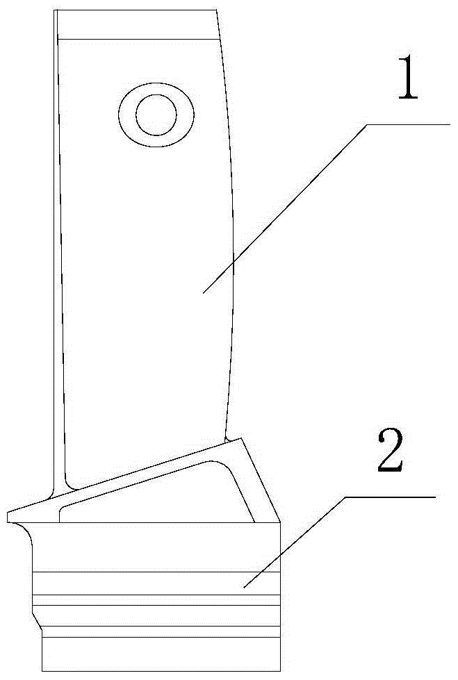
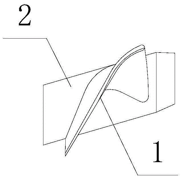
[0034] refer to Figures 1 to 2 As shown, a method of using alloy casting to meet the positioning of workpieces with complex shapes, including turbine blades, the turbine blades are composed of blade body 1 and tenon 2, and includes the following steps in turn:

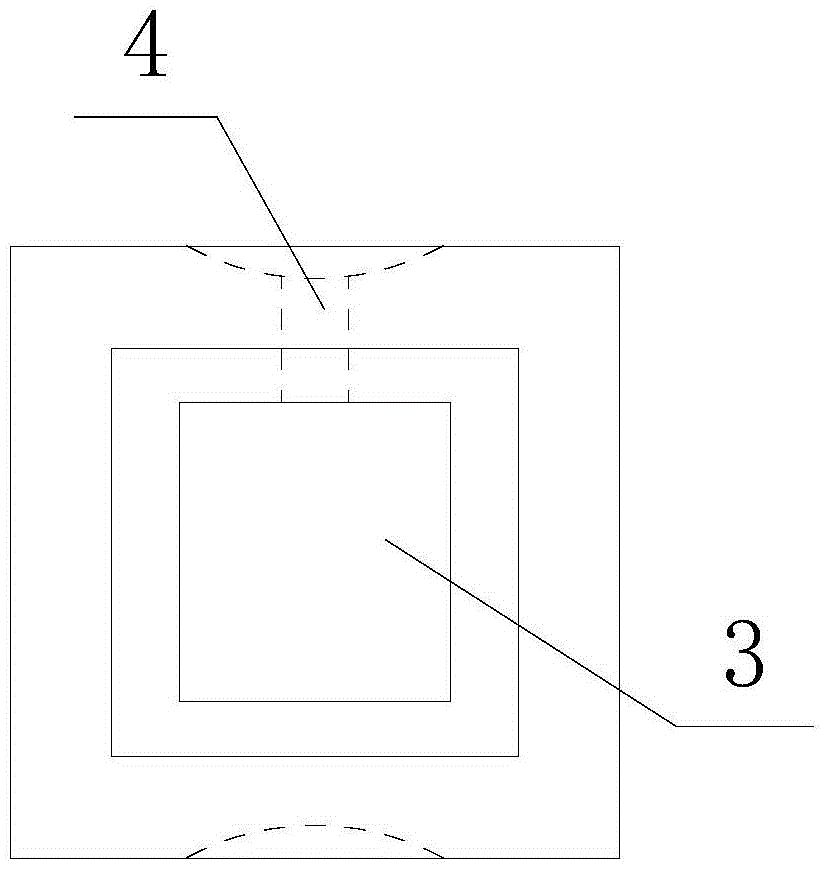
[0035] A. Reference Figures 3 to 9 As shown, the square box and cast tire are prepared: the square box is used to integrate with the turbine blade after pouring to facilitate subsequent processing; the cast tire is used to pour alloys into the other box and the turbine blade.

[0036] The square box is a rectangular frame body, and the hollow part of the rectangular frame body is a square hole 3 for accommodating the airfoil of the turbine blade. The pouring hole 4; the frame body at one end of the square hole on the square box protrudes to form a boss 5, and the frame body at the other end is recessed to form a groove 6.

[0037] The cast tire...


PUM

PropertyMeasurementUnit
melting pointaaaaaaaaaa
densityaaaaaaaaaa

Abstract

The invention discloses a method for meeting the positioning requirement of a complex-shaped workpiece through alloy casting and belongs to the field of machining. The method relates to a turbine blade. The turbine blade is composed of a blade body and a tenon. The method comprises the following steps that a square box and a pouring body are prepared; an upper front template and an upper rear template of the pouring body are taken down; the square box is installed, and the turbine blade is arranged; alloy casting is conducted; the square box is taken out; extra alloy is removed; whether the tenon of the turbine blade is located in the center of the square box or not is detected through a height gauge; if the tenon of the turbine blade is located in the center of the square box, the tenon of the turbine blade is ground through the square box; if the tenon of the turbine blade is not located in the center of the square box, casting is conducted for height adjustment; and after the tenon of the turbine blade is ground, the alloy is melted, the turbine blade is taken out, and the square box and the pouring body are used repeatedly for machining the next turbine blade. By means of the method, the clamping and positioning requirements can be met, installation is convenient, and clamping machining is facilitated.

Description

technical field [0001] The invention belongs to the field of machine processing, and in particular relates to the positioning processing of complex-shaped workpieces. Background technique [0002] In machining, there are some products that are not easy to clamp. Such as figure 1 , 2 The blade body shown in the turbine blade is made of precision casting, and the tenon needs to be ground on a powerful grinding machine. Because the blade body is small, it is not conducive to clamping, and there is a lack of sufficient clamping means for this type of product. Contents of the invention [0003] The object of the present invention is to propose a method for positioning turbine blades of workpieces with complex shapes by using alloy casting, which can meet the requirements of clamping and positioning, achieve convenient installation, and facilitate clamping and processing. [0004] The object of the invention is achieved through the following technical solutions: [0005] A m...

Claims


Application Information

Patent Timeline
Patent Type & Authority Patents(China)
IPC IPC(8): B22C9/22
CPCB22C9/22
Inventor 钟林
Owner SICHUAN CRRC YUCHAI ENGINE CO LTD
Why Eureka
Try Eureka