Automatic stress test drilling machine and working method thereof

A technology of stress testing and working methods, applied in boring/drilling, automatic control devices, drilling/drilling equipment, etc., can solve problems such as long test time, low efficiency, and affecting stress test results, and achieve convenient positioning Accuracy, convenient and accurate operation, and the effect of ensuring stability

Active Publication Date: 2016-03-09
SHANDONG HUAWIN ELECTRICAL & MECHANICAL TECH
View PDF6 Cites 14 Cited by
  • Summary
  • Abstract
  • Description
  • Claims
  • Application Information

AI Technical Summary

Problems solved by technology

However, in actual operation, especially the installation of the drilling device on the surface of the workpiece to be tested or other non-planar, vertical and inclined surfaces often requires two people to cooperate and cooperate with each other, which increases the difficulty of centering and fixing the test device, which is labor

Method used


Image

  • Automatic stress test drilling machine and working method thereof
  • Automatic stress test drilling machine and working method thereof
  • Automatic stress test drilling machine and working method thereof

Examples


Embodiment 1

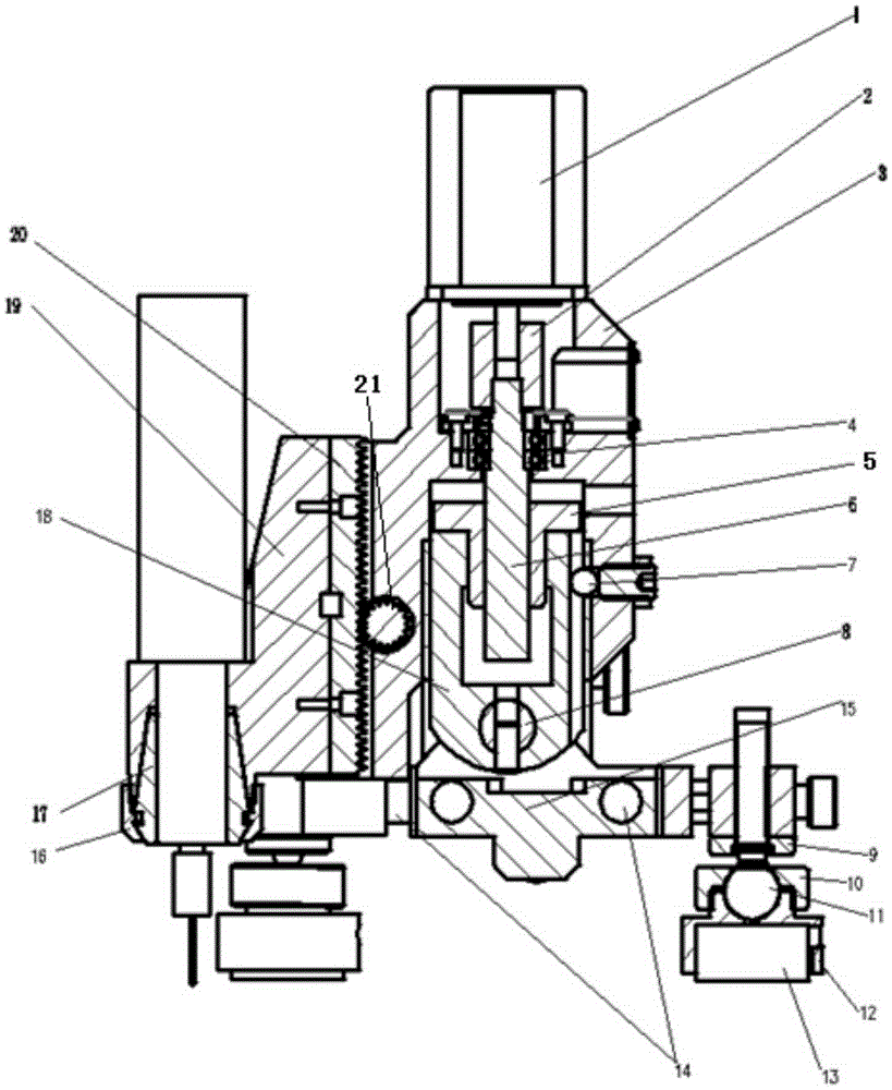
[0045] An automatic stress test drilling machine includes a base and a gun drill part erected by the base, and the gun drill part includes a driving device and a gun drill 27 driven by the driving device.

[0046] The gun drill 27 is connected with the driving device through the gun drill seat 19 .

[0047] The gun drill base 19 is connected with the driving device through a rack 20 and a positioning gear 21 .

[0048] The gun drill 27 is connected to the gun drill seat 19 through the spring collet 17 .

Embodiment 2

[0050] A kind of automatic stress test drilling machine as described in embodiment 1, its difference is that, described driving device comprises the fixed part 18 that is fixedly connected with described base, movable part and the motor 1 that drives movable part to move, and described fixed Part and 18 movable parts are axially connected by transmission shaft.

[0051] The motor 1 is arranged on the movable part, and a screw nut 5 is arranged on the fixed part 18, and a shaft coupling 2 and a lead screw 6 are sequentially connected with the motor 1, and the lead screw 6 is axially arranged in the screw nut 5 and Used in conjunction with the silk mother 5.

Embodiment 3

[0053] An automatic stress test drilling machine as described in Embodiment 2, the difference is that the motor 1 is arranged on the fixed part 18, and the nut 5 is arranged on the movable part, and the motor 1 is sequentially connected with a shaft coupling 2 and a lead screw 6, the lead screw 6 is axially arranged in the screw nut 5 and used in conjunction with the screw nut 5.


PUM


Abstract

The invention discloses an automatic stress test drilling machine. The automatic stress test drilling machine comprises a base and a gun drill part, wherein the gun drill part is erected by the base and comprises a driving device and a gun drill driven by the driving device to move. The automatic stress test drilling machine and the working method thereof, provided by the invention have the advantages that the drilling machine is capable of realizing an automatic driving function in comparison with controlling drilling depth and accuracy manually, and is compact in structure and more convenient and accurate in operation. The gun drill part swings at a certain angle around a pin roll, so that an angle between the gun drill part and a to-be-measured sample surface can be finely adjusted to adapt to stress test drill holes at various positions with complex structures. The drilling machine provided by the invention can realize the adjustment on arranging angle and height of the base through stand bars arranged at the bottom part of a rack plate to ensure the stability of work. The gun drill provided by the invention is fixed by adopting a collet chuck manner, so the high-precision positioning accuracy of the gun drill is much facilitated. According to the automatic stress test drilling machine and the working method thereof, a longitudinal frame and a horizontal frame are used to realize the quick positioning of the gun drill part in all sides in a plane.

Description

technical field [0001] The invention relates to an automatic stress test drilling machine and a working method thereof, belonging to the technical field of material residual stress test. Background technique [0002] In the process of machining, the non-uniform plastic deformation caused by the change of external force and temperature is the main reason for the generation of residual stress. In the process of casting, forging, welding and various cutting processes, the workpiece will be redistributed due to the external force and temperature, which may affect the size and shape accuracy of the parts and the assembly accuracy of the parts, reducing the The fatigue resistance, stress corrosion resistance and creep cracking resistance of parts ultimately affect the performance and service life of machinery and equipment. Therefore, it is crucial to test the stress phase of raw materials, parts or equipment. [0003] There are many methods for testing residual stress, such as ...

Claims


Application Information

Patent Timeline
IPC IPC(8): B23B39/14B23Q1/01B23Q15/22
CPCB23B39/14B23Q1/01B23Q15/22
Inventor 赵显华谢祥科王阳刘秀娟赵志明
Owner SHANDONG HUAWIN ELECTRICAL & MECHANICAL TECH
Why Eureka
Try Eureka