A horizontally stable automatic stress measurement drilling machine and its working method

A working method and level-stable technology, applied in measuring/indicating equipment, manufacturing tools, metal processing equipment, etc., can solve problems such as low efficiency, long test time, and affecting stress test results, and achieve convenient and accurate operation and convenient positioning accuracy , to ensure the effect of stability

Active Publication Date: 2019-05-14
SHANDONG HUAWIN ELECTRICAL & MECHANICAL TECH
View PDF7 Cites 0 Cited by
  • Summary
  • Abstract
  • Description
  • Claims
  • Application Information

AI Technical Summary

Problems solved by technology

However, in actual operation, especially the installation of the drilling device on the surface of the workpiece to be tested or other non-planar, vertical and inclined surfaces often requires two people to cooperate and cooperate with each other, which increases the difficulty of centering and fixing the test device, which is labor-intensive and time-consuming
[0004] At present, the stress test drilling on the market generally uses manual drilling equipment. The drilling is mainly based on the experience of the operator. The drilling accuracy (depth) cannot be guaranteed, which affects the stress test results.
And the test time is long and the efficiency is low

Method used


Image

  • A horizontally stable automatic stress measurement drilling machine and its working method
  • A horizontally stable automatic stress measurement drilling machine and its working method
  • A horizontally stable automatic stress measurement drilling machine and its working method

Examples


Embodiment 1

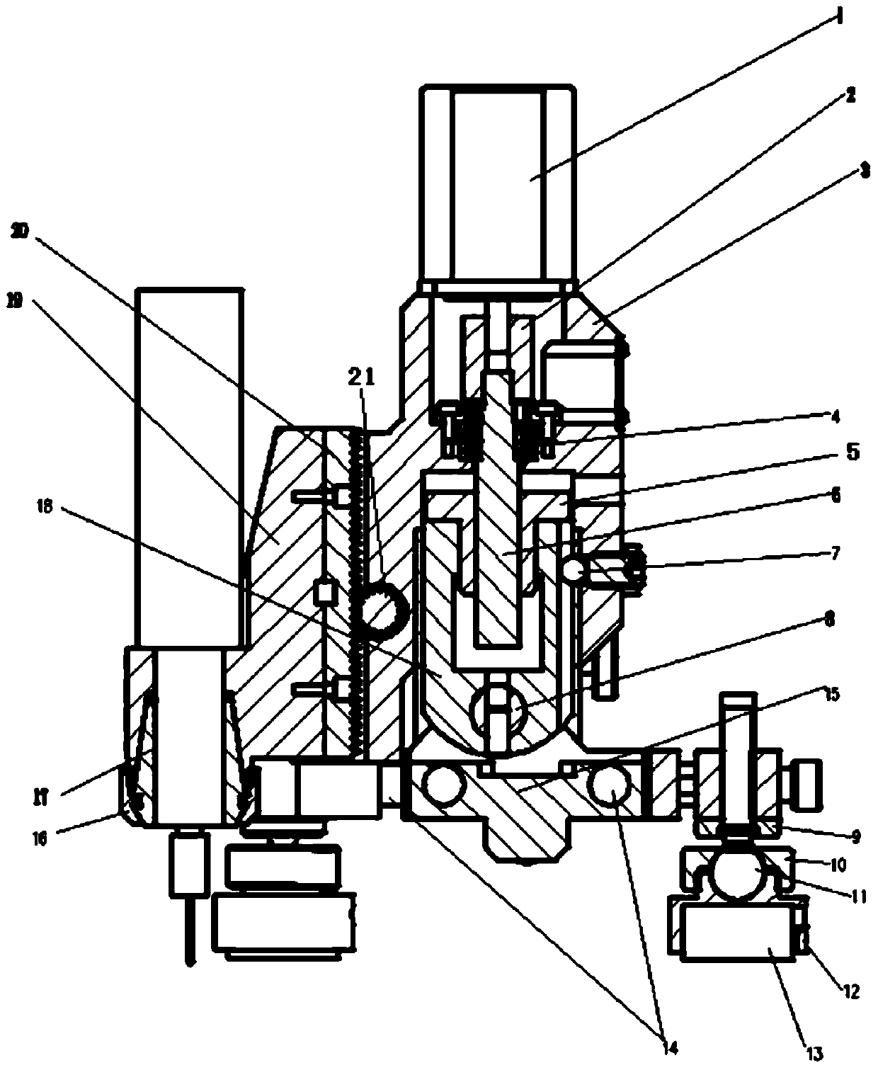
[0047] A horizontally stable automatic stress measurement drilling machine, comprising a base and a gun drill part erected by the base, the gun drill part including a driving device and a gun drill 27 driven by the driving device;

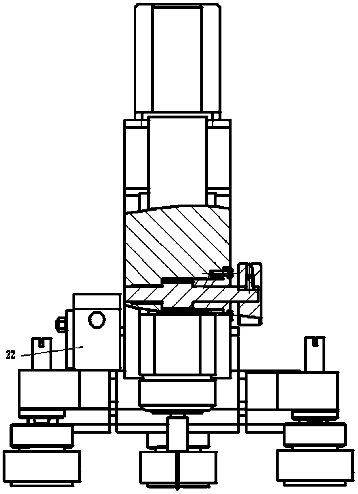
[0048] The base also includes at least three legs 28 for adjusting the angle, which are arranged on the bottom of the rack 29;

[0049]The support foot 28 includes a ball stud 11 connected to the rack 29, a compression nut 10, a magnetic base 12 and a magnetic chuck 13, and the ball stud 11 is connected by a lock nut 9 arranged at the bottom of the rack 29 , the ball head of the ball head rod 11 cooperates with the compression nut 10 and the magnetic base 12 so that the magnetic base 12 is arranged at multiple angles; a second spirit level 33 is arranged on the horizontal plane of the base.

Embodiment 2

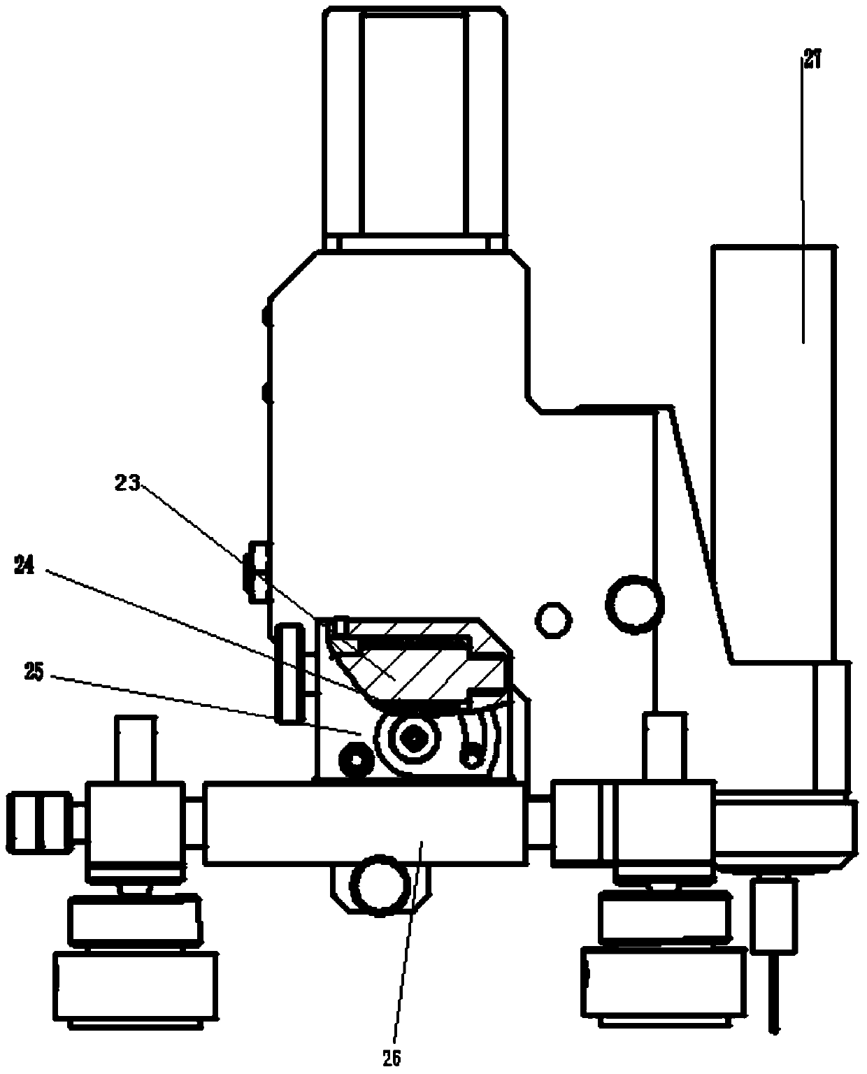
[0051] A horizontally stable automatic stress measurement drilling machine as described in Embodiment 1, the difference is that the plane of the top end of the gun drill 27 is perpendicular to the axial direction of the gun drill 27, and at the top of the gun drill 27 The plane is provided with a first spirit level 34 .

Embodiment 3

[0053] A horizontally stable automatic stress measurement drilling machine as described in Embodiments 1 and 2, the difference is that the gun drill 27 is connected to the driving device through the gun drill base 19 . The gun drill base 19 is connected with the driving device through a rack 20 and a positioning gear 21 .


PUM


Abstract

A horizontally-stabilized automatic stress measurement drilling machine comprises a base and a gun drill part erected by the base, wherein the gun drill part comprises a driving device and a gun drill driven to move by the driving device; the base comprises at least three support legs used for adjusting the angle and arranged at the bottom of a frame disc; each support leg comprises a ball head rod, a gland nut, a magnetic base and a magnetic suction disc which are connected with the frame disc; the ball head rods are connected through locking nuts arranged at the bottom of the frame disc; the ball head of each ball head rod is matched with the corresponding magnetic base through the corresponding gland nut to enable the magnetic base to be arranged in multiple angles; a second level gauge is arranged on the horizontal plane of each magnetic base. Compared with a drilling machine that the drilling depth and accuracy are controlled manually, the drilling machine provided by the invention can realize an automatic driving function and is compact in structure; the mounting angle of the working base is rapidly adjusted through the level gauges to enable the drilling machine to work normally and horizontally, so that the drilling perpendicularity to the horizontal plane is ensured and the stress test accuracy is guaranteed.

Description

technical field [0001] The invention relates to a horizontally stable automatic stress measuring drilling machine and a working method thereof, belonging to the technical field of material residual stress testing. Background technique [0002] In the process of machining, the non-uniform plastic deformation caused by the change of external force and temperature is the main reason for the generation of residual stress. In the process of casting, forging, welding and various cutting processes, the workpiece will be redistributed due to the external force and temperature, which may affect the size and shape accuracy of the parts and the assembly accuracy of the parts, reducing the The fatigue resistance, stress corrosion resistance and creep cracking resistance of parts ultimately affect the performance and service life of machinery and equipment. Therefore, it is crucial to test the stress section of the raw material or part. [0003] There are many methods for testing resid...

Claims


Application Information

Patent Timeline
Patent Type & Authority Patents(China)
IPC IPC(8): B23Q17/20
CPCB23Q17/20
Inventor 赵显华谢祥科王阳刘秀娟赵志明
Owner SHANDONG HUAWIN ELECTRICAL & MECHANICAL TECH
Why Eureka
Try Eureka