A tension roller grinding device

A tension roller and grinding roller technology, applied in the field of coiler tension roller processing tools, can solve the problems of uneven grinding of the roller surface, reduce the service life of the tension roller, increase the production cost, etc., so as to reduce the damage to the process stability, The effect of reducing labor intensity and processing time

Active Publication Date: 2018-02-06
BENGANG STEEL PLATES
View PDF8 Cites 0 Cited by
  • Summary
  • Abstract
  • Description
  • Claims
  • Application Information

AI Technical Summary

Problems solved by technology

[0004] 1) The security is not high
Personnel are required to enter the equipment during online grinding. It can be seen that the internal space of the tension roller is too narrow, and the safety cannot be effectively guaranteed when grinding in a narrow space.
[0005] 2) The work is intense and time-consuming
Due to working in a narrow and confined space, the efficiency of manual grinding is not high, and sometimes it needs to be repeated
[0006] 3) Insufficient grinding precision
Grinding with grinding stones manually, on the one hand, the grinding of the roller surface is uneven, and the grinding accuracy cannot be effectively guaranteed, so that the elimination of product defects cannot be guaranteed
On the other hand, the service life of the tension roller is reduced, and the consumption of grinding stone is large, resulting in an increase in production cost
[0007] 4) Due to the high rigidity of the connection between the secondary heat and continuous casting, the flexibility of production coordination is poor, and the manual grinding of the tension roll needs to be stopped for cooperation. After recovery, the stop of rolling will cause damage to the process stability, which will have a negative impact on production continuity and product quality very big

Method used


Image

  • A tension roller grinding device
  • A tension roller grinding device
  • A tension roller grinding device

Examples


Embodiment Construction

[0036] In order to make the object, technical solution and advantages of the present invention more clear, the present invention will be further described in detail below in conjunction with the examples. It should be understood that the specific embodiments described here are only used to explain the present invention, not to limit the present invention.

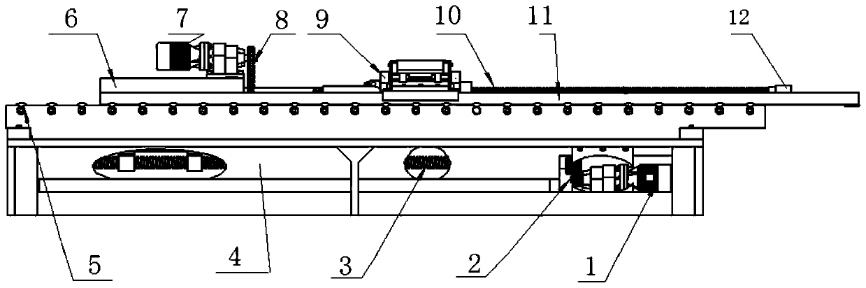
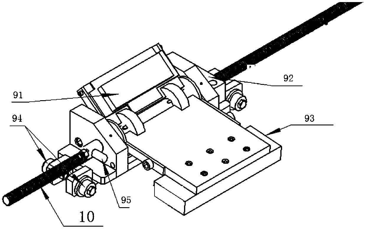
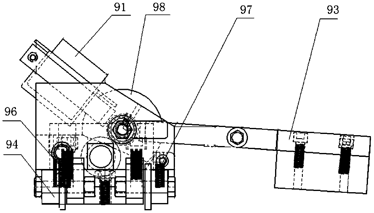
[0037] see figure 1 combine figure 2 , a tension roller grinding roller device, the device includes: a lower bracket 4, the lower bracket 4 plays a supporting role, is a long strip structure, its upper surface has a slide rail support wheel 5 with a boss, on the slide rail A slide rail 11 is arranged on the support wheel 5, and the slide rail 11 is driven to slide on the slide rail support wheel 5 through the slide rail travel driving mechanism installed on the lower bracket, and a trolley 9 is installed on the slide rail 11, and the slide rail 11 is a double track , wheels are set under the trolley 9, to realize that th...


PUM


Abstract

The invention relates to the field of reeling machine tension roller treatment tools, in particular to a tension roller grinding device. The device comprises a lower support, a sliding rail, a trolley, a sliding rail walking drive mechanism and a trolley walking drive mechanism. The sliding rail is arranged on the lower surface of the lower support and walks on the lower support. The trolley is arranged on the sliding rail and provided with millstone and walks on a track on the sliding rail. The sliding rail walking drive mechanism is arranged on the lower support and drives the sliding rail installed on the lower support to walk. The trolley walking drive mechanism is installed on the sliding rail and connected with the trolley through a lead screw, and the trolley is driven to walk on the track. When rollers are produced and replaced or rolling must be stopped to treat concave-convex marks, manual operation can be replaced to rapidly and automatically grind the tension rollers, labor intensity is lowered, and safety and reliability are achieved.

Description

technical field [0001] The invention relates to the field of tension roller processing tools for coilers, specifically a tension roller grinding device. Background technique [0002] Due to the inevitable friction between the hot-rolled strip and the side guide plate of the coiler during the normal production process, the scraped iron filings are brought in; the tail flick that occurs during the strip rolling process; the biting impact of the strip head Both can cause foreign matter to adhere to the surface of the tension roller and cause pit-like printing quality defects on the surface of the strip. [0003] The existing grinding method is to rely on the operator to manually grind with a grindstone, and the manual online grinding of the tension roller has the following disadvantages: [0004] 1) The security is not high. Personnel are required to enter the equipment during online grinding. It can be seen that the internal space of the tension roller is too narrow, and the...

Claims


Application Information

Patent Timeline
Patent Type & Authority Patents(China)
IPC IPC(8): B24B5/16B24B5/35B24B47/04B24B47/12
CPCB24B5/167B24B5/35B24B47/04B24B47/12
Inventor 陈亮荆涛张猛程宏远张新枫郑广德张策
Owner BENGANG STEEL PLATES
Why Eureka
Try Eureka