
Polishing device and method of sapphire wafer
A technology for sapphire wafers and polishing devices, which is applied in the direction of grinding devices, grinding/polishing equipment, grinding machine tools, etc., can solve the problems of poor flatness of the wafer surface, unstable polishing removal rate, uneven polishing liquid, etc., and achieve Reduce uneven stirring, reduce scratches and scratches, good uniformity effect
Patent Information
- Authority / Receiving Office
- CN · China
- Current Assignee / Owner
- Publication Date
- 2016-03-09
- Estimated Expiration
- Not applicable · inactive patent
Smart Images
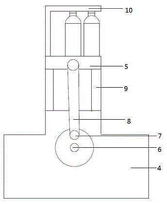
Figure 1 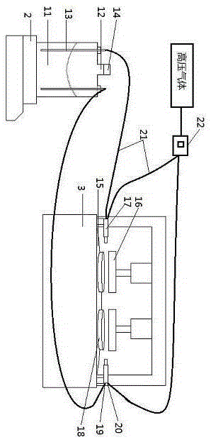
Figure 2
Abstract
Description
technical field
[0001] The invention relates to the field of processing sapphire substrates, in particular to a polishing device for a sapphire wafer and a polishing method thereof. Background technique
[0002] Diamond liquid polishing is a very important process in the manufacture of sapphire wafers. It determines whether the technical parameters of TTV, LTV, and WARP after sapphire polishing meet customer needs. The general diamond polishing liquid mainly The composition is made of 80-90% alkanes and a small amount of dispersed thixotropic agents, pH regulators, surfactants, and 0.1-1% diamond differential modulation. The existing technology is applied, and the diamond in the diamond polishing liquid The micropowder is affected by gravity in the liquid, easy to precipitate, and has poor suspension. After being artificially shaken and stirred for a period of time, a part of the diamond micropowder will settle at the bottom of the container, resulting in uneven polishing li...
Examples
Embodiment Construction
[0022] A polishing device for a sapphire wafer as shown in the figure is characterized in that it includes a vibrator 1, a heating magnetic stirrer 2 and a polishing machine 3, and the vibrator 1 includes a base 4, a throwing seat 5, a motor 6, an eccentric Wheel 7 and connecting rod 8, described base 4 is provided with 4 sliding shafts 9, and described sliding shaft 9 is the linear optical axis that vertically sets, and the both sides of described throwing seat 5 fits on sliding shaft 9 , the throwing seat 5 is provided with a fixed block 10, the motor 6 is arranged in the base 4, the eccentric wheel 7 is fixedly connected with the transmission end of the motor 6, and the upper end of the connecting rod 8 is connected to one of the throwing seat 5. The side is hinged, and the lower end is hinged with the eccentric wheel 7 to realize the vertical movement of the throwing seat 5;
[0023] The heating magnetic stirrer 2 includes a stirring container 11, the stirring container 11...