Distributed multi-rotor-wing unmanned aerial vehicle system with heavy load and long endurance

A multi-rotor UAV, distributed technology, applied in the direction of rotorcraft, unmanned aircraft, motor vehicles, etc., can solve the restrictions on the application and development of multi-rotor UAVs, inconvenient maintenance, transportation and mass production, flight Problems such as limited time and load capacity, etc., to achieve the effect of easy maintenance, space saving and weight reduction

Inactive Publication Date: 2016-03-09
张利国
View PDF7 Cites 11 Cited by
  • Summary
  • Abstract
  • Description
  • Claims
  • Application Information

AI Technical Summary

Problems solved by technology

[0002] At present, most civilian multi-rotor aircraft are driven by motors. Because the energy density of batteries is much lower than that of fossil fuels such as gasoline, the flight time and load capacity of current multi-rotor aircraft are very limited. The longest flight time does not exceed 30 minutes, and the maximum load is not More than 20Kg, which greatly limits the application and development of multi-rotor drones
In addition, the current drones generally adopt rigid connection or integral structure design, which is difficult to disassemble and assemble, and is not convenient for maintenance, transportation and batch production

Method used


Image

  • Distributed multi-rotor-wing unmanned aerial vehicle system with heavy load and long endurance
  • Distributed multi-rotor-wing unmanned aerial vehicle system with heavy load and long endurance
  • Distributed multi-rotor-wing unmanned aerial vehicle system with heavy load and long endurance

Examples


Embodiment Construction

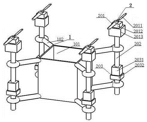
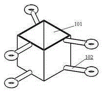
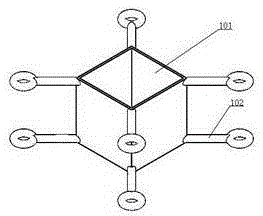
[0023] Such as Figure 1 to Figure 9 As shown, a distributed heavy-duty long-endurance multi-rotor UAV system includes an independent fuselage 1 and a distributed fuselage 2. The independent fuselage 1 includes a standard box 101 and a box arm 102. Each standard box 101 is equipped with at least 3 box arms, and the box arm 102 adopts an upper and lower double box arm structure, and the distributed body 2 is fixed on the box arm 102 of the independent body 1; the distributed body 2 includes Power system 201, machine arm 202 and electronic system 203, described power system 201 is installed on the upper end of machine arm 202, and electronic system 203 is installed on the lower end of machine arm 202; Described power system 201 comprises rotor 2011, engine 2012, oil pump 2013 , the fuel tank 2014 and the steering gear 2015, the rotor 2011 is connected to the engine 2015 and located above the steering gear 2015, the oil pump 2013 is connected to the fuel tank 2014 and located bel...


PUM


Abstract

The invention belongs to the fields of structural design and flight control of a multi-rotor-wing aircraft, and particularly relates to a distributed multi-rotor-wing unmanned aerial vehicle system with a heavy load and long endurance. The distributed multi-rotor-wing unmanned aerial vehicle system comprises an independent fuselage and distributed vehicle bodies, wherein the independent fuselage comprises standard boxes and box arms; each stand box is at least provided with three box arms; the distributed vehicle bodies are fixed on the box arms of the independent fuselage; each of the distributed vehicle bodies comprises a power system, a vehicle arm and an electronic system, wherein the power systems are mounted at the upper ends of the vehicle arms, and the electronic systems are mounted at the lower ends of the vehicle arms; each of the power systems comprises rotor wings, an engine, an oil pump, an oil tank and a steering engine; each of the electronic systems comprises a flight control system and a power supply module. The independent fuselage and the distributed vehicle bodies are designed in a high-modularized way, so that quick matching, disassembling and assembling can be realized; the unmanned aerial vehicle system is convenient to repair, maintain, transport and produce in batches; the power systems adopt direct oil-driving structures, and the engines directly drive the rotor wings, so that the structure is simplified, the weight is reduced, the endurance is greatly prolonged, and the load is enlarged.

Description

technical field [0001] The invention belongs to the field of structural design and flight control of multi-rotor aircraft, in particular to a distributed heavy-load long-endurance multi-rotor UAV system. Background technique [0002] At present, most civilian multi-rotor aircraft are driven by motors. Because the energy density of batteries is much lower than that of fossil fuels such as gasoline, the flight time and load capacity of current multi-rotor aircraft are very limited. The longest flight time does not exceed 30 minutes, and the maximum load is not More than 20Kg, which greatly limits the application and development of multi-rotor drones. In addition, current drones generally adopt rigid connection or integral structure design, which is difficult to disassemble and assemble, and is not convenient for maintenance, transportation and mass production. Contents of the invention [0003] In order to overcome the shortcomings and deficiencies in the prior art, the pre...

Claims


Application Information

Patent Timeline
Patent Type & Authority Applications(China)
IPC IPC(8): B64C27/08B64C27/14
CPCB64C27/08B64C27/14B64U50/11B64U10/10
Inventor 张利国陈浩姜文辉郭向群王子琦
Owner 张利国
Why Eureka
Try Eureka