Electrochemical battery and manufacturing method therefor

An electrochemical and battery technology, applied in the field of electrochemical batteries, can solve problems such as packaging failure, reduce the area, reduce the total amount of glue overflow, and save the amount of glue

Active Publication Date: 2016-03-09
GUANGDONG ZHUGUANG NEW ENERGY TECH
5 Cites 8 Cited by

AI-Extracted Technical Summary

Problems solved by technology

However, because this method uses flowable glue, in the actual production process, the ...

Abstract

The invention belongs to the field of electrochemical batteries and particularly relates to an electrochemical battery. The electrochemical battery comprises a bare battery cell, an electrolyte solution and an external package, wherein a rubber tape layer is arranged between the bare battery cell and the external package; the rubber tape layer comprises a base material and a bonding layer; the base material is 0.5-500 microns in thickness h1, and when the base material is heated to above 45 DEG C, the base material shows the bonding performance; the bonding layer is 0.5-500 microns in thickness h2, and when the temperature is lower than or equal to 45 DEG C, the bonding layer shows the bonding performance; and a rubber tape (before glue overflow) covers 2-90% of the surface area of the bare battery cell. The electrochemical battery has the advantages that the bonding layer has bonding force at a relatively low temperature, so that the operation is convenient when the battery cell is manufactured; the bonding layer is pasted to the surface of the bare battery cell or/and the inner side of the external package; and the base material shows bonding force after being heated, so that a bonding area between the bare battery cell and the external package can be effectively enlarged, the coverage area of the rubber tape on the bare battery cell is reduced, the glue consumption is reduced, the total amount of overflowed glue is reduced, and a mucilage glue layer is prevented from being diffused to a degassing packaging edge to influence the packaging effect.

Application Domain

Assembling battery machinesFinal product manufacture +1

Technology Topic

ElectrochemistryEngineering +4

Image

  • Electrochemical battery and manufacturing method therefor

Examples

  • Experimental program(12)
  • Comparison scheme(2)
  • Effect test(1)

Example Embodiment

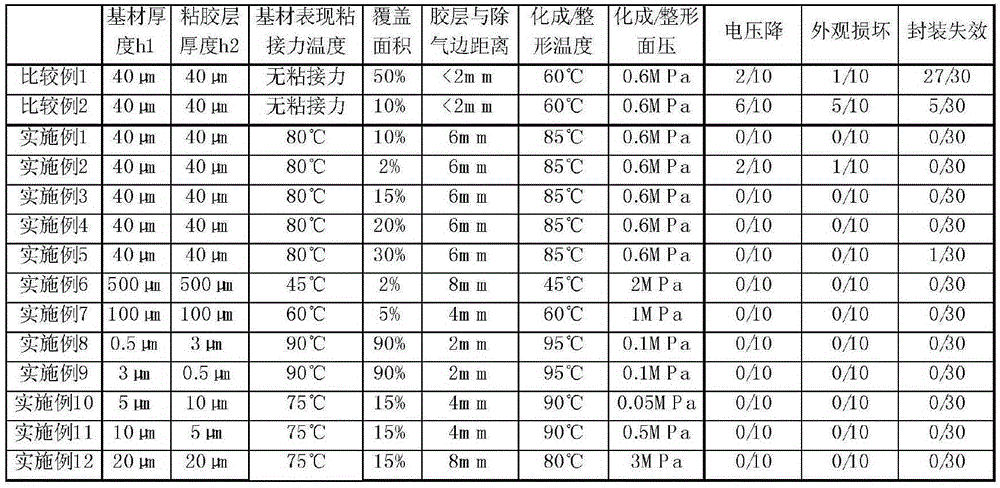
[0032] Embodiment 1, different from Comparative Example 2, this embodiment comprises the following steps:
[0033] Adhesive layer setting: select a modified polypropylene film with a thickness of 40 μm as the base material (adhesive force is exhibited when the temperature is 80° C.), and a polyurethane tape with a thickness of 40 μm is used as the adhesive layer; paste the tape on The surface of the above-mentioned bare cells, and the tape covers 10% of the surface area of ​​the bare cells, and the distance between the tape and the side of the battery degassing package is 6mm; then put the bare cells in the outer packaging bag for top sealing and side sealing;
[0034] Finished battery preparation: Dry the above-mentioned top-sealed cells, inject liquid, and perform fixture formation at 85°C and 0.6 MPa after the electrolyte is fully infiltrated, and then shape, degas, and seal to obtain finished cells.
[0035]The rest are the same as those of Comparative Example 2, and will not be repeated here.

Example Embodiment

[0036] Embodiment 2, different from Embodiment 1, this embodiment includes the following steps:
[0037] Adhesive layer setting: select a modified polypropylene film with a thickness of 40 μm as the base material (adhesive force is exhibited when the temperature is 80° C.), and a polyurethane tape with a thickness of 40 μm is used as the adhesive layer; paste the tape on The surface of the above-mentioned bare cells, and the tape covers 2% of the surface area of ​​the bare cells, and the distance between the tape and the side of the battery degassing package is 6mm; then put the bare cells in the outer packaging bag for top sealing and side sealing;
[0038] The rest are the same as in Embodiment 1 and will not be repeated here.

Example Embodiment

[0039] Embodiment 3, different from Embodiment 1, this embodiment includes the following steps:
[0040] Adhesive layer setting: select a modified polypropylene film with a thickness of 40 μm as the base material (adhesive force is exhibited when the temperature is 80° C.), and a polyurethane tape with a thickness of 40 μm is used as the adhesive layer; paste the tape on The surface of the above-mentioned bare cells, and the tape covers 15% of the surface area of ​​the bare cells, and the distance between the tape and the side of the battery degassing package is 6mm; then put the bare cells in the outer packaging bag for top sealing and side sealing;
[0041] The rest are the same as in Embodiment 1 and will not be repeated here.

PUM

PropertyMeasurementUnit
Thickness0.5 ~ 500.0µm
Thickness3.0 ~ 100.0µm
Thickness40.0µm

Description & Claims & Application Information

We can also present the details of the Description, Claims and Application information to help users get a comprehensive understanding of the technical details of the patent, such as background art, summary of invention, brief description of drawings, description of embodiments, and other original content. On the other hand, users can also determine the specific scope of protection of the technology through the list of claims; as well as understand the changes in the life cycle of the technology with the presentation of the patent timeline. Login to view more.

Similar technology patents

Light-emitting element transfer assembly and light-emitting element transfer method

PendingCN114823458Aincrease bonding areaImprove adhesion
Owner:CHENGDU VISTAR OPTEOLECTRONICS CO LTD

Sticky steel glue for concrete and preparation process thereof

InactiveCN108070335Aincrease bonding areaStrong fastening performance
Owner:ANHUI KUNDA CHEM ANCHORAGE

Micro-channel inlet cover plate and preparation method and use method thereof

ActiveCN112169851Aincrease bonding areaImprove connection strength
Owner:INST OF MICROELECTRONICS CHINESE ACAD OF SCI

Cigarette packet box gluing and folding device

ActiveCN112549640ASimplify the subsequent process flowincrease bonding area
Owner:CHINA TOBACCO MACHINERY TECH CENT

Classification and recommendation of technical efficacy words

  • reduce area
  • increase bonding area

Semiconductor memory device

InactiveUS20110260158A1reduce numberreduce area
Owner:SEMICON ENERGY LAB CO LTD

Bidirectional PNPN silicon-controlled rectifier

ActiveUS20090236631A1reduce area
Owner:AMAZING MICROELECTRONICS

Semiconductor device

ActiveUS20070296020A1reduce area
Owner:RENESAS ELECTRONICS CORP

Ceramic electronic component and method for manufacturing the same

ActiveUS20150016018A1increase bonding areareduce connection resistance
Owner:MURATA MFG CO LTD

Junction structure and method of manufacturing the same

InactiveUS20090108474A1reduce surface roughnessincrease bonding area
Owner:PANASONIC CORP

Surface processing solution for manufacturing solid electrolytic capacitor

InactiveCN101819887AUniform bondingincrease bonding area
Owner:FUJIAN GUOGUANG ELECTRONICS SCI & TECHCO

Water-based polyvinylidene fluoride coating slurry, battery diaphragm and preparation method of slurry

ActiveCN111205707Aincrease bonding areaImprove bonding performance
Owner:武汉中兴创新材料技术有限公司

Lead pin for package substrate and semiconductor package printed circuit board including the same

InactiveUS20120153473A1increase bonding areaoperational reliability be improve
Owner:SAMSUNG ELECTRO MECHANICS CO LTD
Why Eureka
Try Eureka