A ground fault current detection circuit and method

A technology of current detection circuit and ground fault, which is applied in the field of ground fault current detection circuit, can solve the problems of unsatisfactory protection accuracy requirements and complex signal conditioning circuit, and achieve the effects of low cost, high protection accuracy, and fewer electronic devices

Active Publication Date: 2017-10-20
JIANGSU DAQO KFINE ELECTRIC
View PDF5 Cites 1 Cited by
  • Summary
  • Abstract
  • Description
  • Claims
  • Application Information

AI Technical Summary

Problems solved by technology

[0006] In the conventional single-coil scheme, the grounding protection function is realized, such as the US patent US6407894B1, the current sampling resistor samples the AC signal before the rectification, and in the signal processing process of the op-amp, the op-amp needs to use an op-amp with isolation Or use positive and negative power supplies, and the signal needs to be processed by two stages of operational amplifiers, and the signal conditioning circuit is relatively complicated
At present, a half-wave is often used for grounding protection in relays. Since half-wave is used for effective value calculation, it cannot meet the requirements of high protection precision applications.

Method used


Image

  • A ground fault current detection circuit and method
  • A ground fault current detection circuit and method
  • A ground fault current detection circuit and method

Examples


Embodiment Construction

[0029] The present invention will be described in further detail below in conjunction with the accompanying drawings.

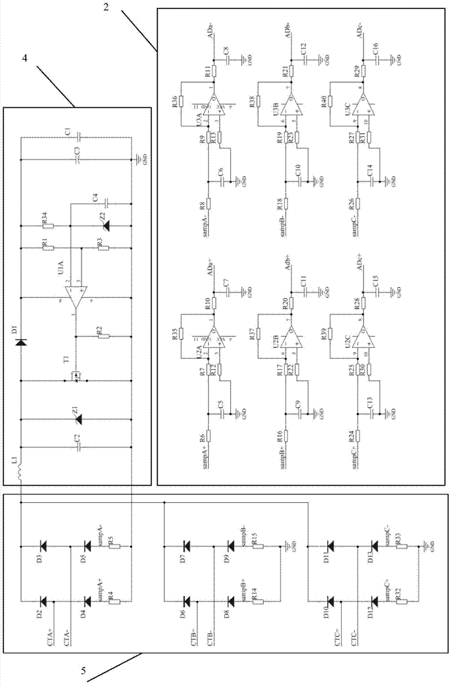
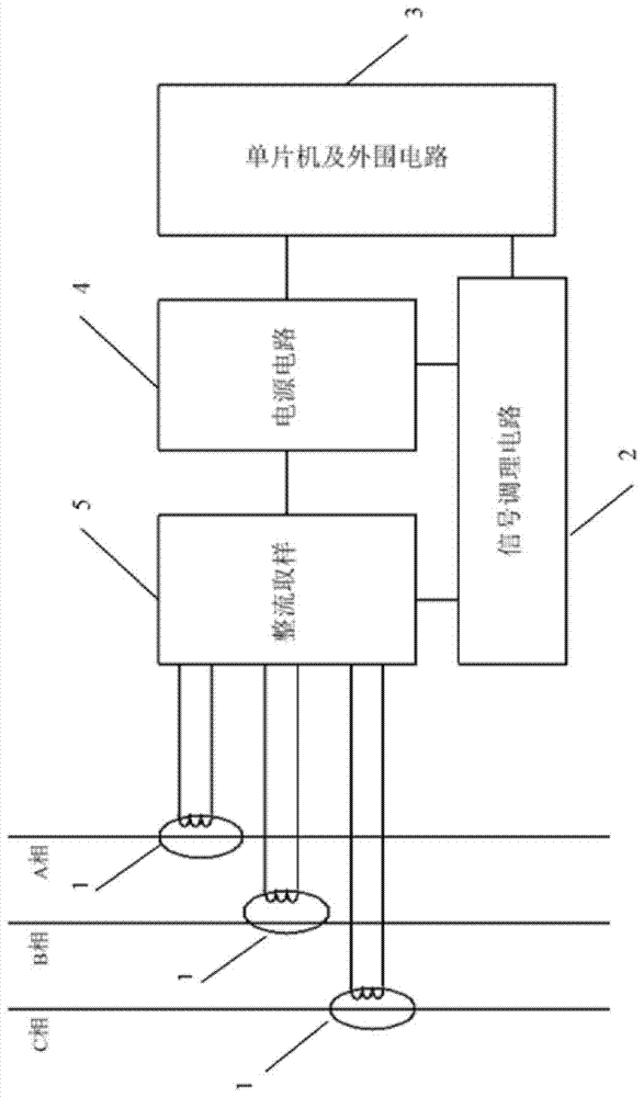
[0030] Such as figure 1 , 2As shown, the present invention provides a ground fault current detection circuit, which consists of five parts: current transformer, rectification sampling circuit, power supply circuit, signal conditioning circuit, single-chip microcomputer and peripheral circuit. The current transformers are A-phase, B-phase, C-phase current transformers or A-phase, B-phase, C-phase, N-phase current transformers. The output current signal of the current transformer is directly connected to the full-bridge rectifier circuit composed of diodes. The output current signal of the current transformer is only used for current detection, and also provides energy for the power supply circuit and other circuits. The full-bridge rectifier circuit includes sampling resistors R4, R5, R14, R15, R32, R33, diodes D2, D3, D4, D5, D6, D7, D8, D9, D10, D11, D12, ...


PUM


Abstract

The invention relates to an earth fault current detection circuit and method. A current transformer outputs a current signal to be directly connected to a full-bridge rectifier circuit formed by diodes; CTA+ and CTA- are connected to a rectifier bridge formed by diodes D2, D3, D4 and D5; CTB+ and CTB- are connected to a rectifier bridge formed by diodes D6, D7, D8 and D9; CTC+ and CTC- are connected to a rectifier bridge formed by diode D10, D11, D12 and D13; and each diode are connected with an acquisition resistor in series, adopts a fixed-frequency sampling mode, waveforms of phases A, B and C are superposed through a software algorithm, and an earth fault current effective value is calculated by adoption of a well-known effective value method. The circuit provided by the invention is simple in principle, low in cost and high in protection precision, and is particularly suitable for electrical appliance protection switches with a relatively high requirement for space volume and relatively small rated power.

Description

technical field [0001] The invention relates to a ground fault current detection circuit and method, in particular to a circuit breaker or an overload relay for a low-voltage power distribution system. Background technique [0002] The so-called ground fault refers to the direct contact short circuit of the external leakage and conductive parts relative to or related to the ground, such as equipment casings, pipes and structures. Compared with the general short-circuit form, although the effective value of the short-circuit current is not very large, it is enough to cause personal electric shock casualties and fire accidents, and the consequences are extremely serious. Indirect contact electric shock accidents caused by ground faults are the most common electric shock accidents, and ground-to-ground arcs and electric sparks caused by ground faults are the most common sources of electrical short circuit ignition. When a ground fault occurs, the protective device must cut off...

Claims


Application Information

Patent Timeline
Patent Type & Authority Patents(China)
IPC IPC(8): H02H9/08G01R31/08
Inventor 刘彬戴玮马云鹏王兴刚
Owner JIANGSU DAQO KFINE ELECTRIC
Why Eureka
Try Eureka