
Electronic Discharge Machine

A technology of electric discharge machine and machining fluid, which is applied in the direction of electric processing equipment, metal processing equipment, manufacturing tools, etc., can solve the problems of high cost and complicated device structure, and achieve the effect of simple structure and cheap ion replacement ability

Inactive Publication Date: 2016-03-16
FANUC LTD
View PDF6 Cites 4 Cited by
  • Summary
  • Abstract
  • Description
  • Claims
  • Application Information

AI Technical Summary

Problems solved by technology

[0007] However, in the conventional method, it is necessary to prepare detectors before and after the ion exchanging device, so there is a problem that the structure of the whole device becomes complicated and the cost becomes high.

Method used


Image

  • Electronic Discharge Machine
  • Electronic Discharge Machine
  • Electronic Discharge Machine

Examples


Embodiment Construction

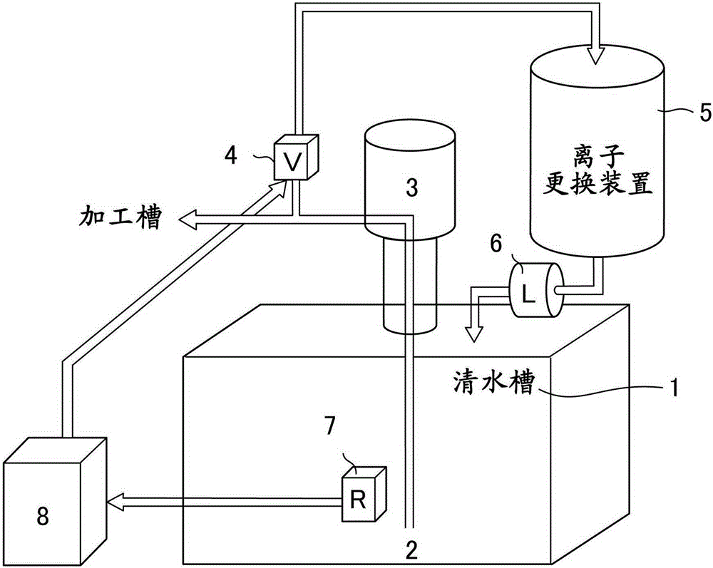
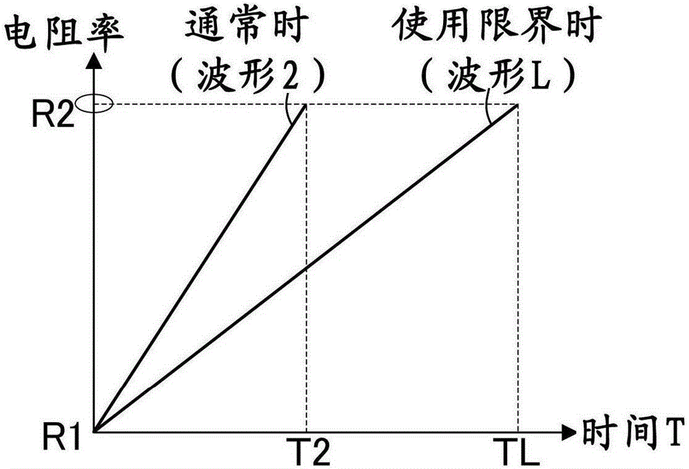
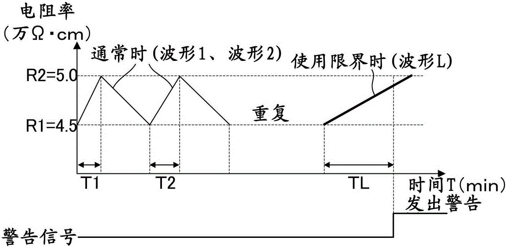
[0020] The basic structure and figure 1 The conventional electric discharge machine shown has the same structure. In this embodiment, during the period when the machining fluid 2 passes through the ion exchange device 5, the resistivity of the machining fluid 2 in the clean water tank 1 is detected by the resistivity detector 7, and the average slope of the resistivity value is recorded. If the average slope is low If it is less than a predetermined value, it is determined that the replacement time of the ion exchange device 5 has come, and a warning is issued to the operator.

[0021] exist figure 1 In the process, the working fluid 2 stored in the clean water tank 1 is pumped by the pump 3 and supplied to the processing tank. At this time, when the resistivity value of the machining fluid 2 detected by the resistivity detector 7 is lower than a predetermined allowable range, the control device 8 controls the switching valve 4, thereby supplying the machining fluid 2 to the...


PUM


Abstract

An electric discharge machine for changing a specific resistance of a working fluid by flowing the working fluid through a circulation line including an ion-exchange device, the electric discharge machine includes a specific resistance detection unit configured to detect a specific resistance of the working fluid, a flow time measuring unit configured to measure flow time of the working fluid into the ion-exchange device, and a determination unit configured to determine that the ion-exchange device reaches a life end, when change value of the specific resistance of the working fluid is out of the predetermined range.

Description

technical field [0001] The present invention relates to an electrical discharge machine using conductive machining fluid, and in particular to life judgment of its ion exchange device. Background technique [0002] In an electric discharge machine using a conductive machining fluid, the resistivity of the machining fluid is adjusted within a fixed range using an ion exchange device in order to perform stable machining. exist figure 1 represents the existing electric discharge machine. In this figure, reference numeral 1 is a clean water tank, reference numeral 2 is a machining fluid (clear water), reference numeral 5 is an ion exchange device, reference numeral 3 is a supply pump for supplying processing fluid to the processing tank or ion exchange device, and reference numeral 4 is a switching valve. Symbol 6 is a flow meter, symbol 7 is a resistivity detector, and symbol 8 is a control device. [0003] Use it like this figure 1 electric discharge machine. The resistiv...

Claims


Application Information

Patent Timeline
Patent Type & Authority Applications(China)
IPC IPC(8): B23H1/00B23H1/10B23H11/00
CPCB23H1/10B01J49/85C02F1/008C02F1/42C02F2103/16C02F2209/05C02F2209/445B23H1/08
Inventor 韩楠川原章义中岛廉夫
Owner FANUC LTD
Learn More