Plastic pipe surface treatment equipment

A technology of surface treatment and plastic pipe fittings, which is applied in the field of plastic pipe fitting surface treatment equipment, can solve the problems that the grinding head mechanism cannot move up and down, affects the production quality of steel pipes, and limits the use process, and achieves light weight, high repeatability, and avoids use. The effect of restriction

Inactive Publication Date: 2016-03-16
CHONGQING XINYONG LIGHTINGS FACTORY
View PDF0 Cites 1 Cited by
  • Summary
  • Abstract
  • Description
  • Claims
  • Application Information

AI Technical Summary

Problems solved by technology

There are many disadvantages in this way, such as: the staff will be fatigued during product processing, which will affect the safety of production. Due to the manual clamping and placement, it is easy to cause personal injury. The existing feeding mechanism has a complex structure and is inconvenient to operate. Human factors affect the quality of products during product processing
And the current grinding head mechanism cannot move up and down, the use process is greatly restricted, and the applicability is low
At the same time, when the plastic pipe fittings are polished and polished, the fixing method is mostly manual grasping, which not only wastes physical strength, but also tends to cause insecure grasping
And with the widespread use of plastic pipe fittings, there are more and more requirements for plastic pipe fittings, and after the surface treatment of plastic pipe fittings, it is necessary to measure the wall thickness of plastic pipe fittings to achieve accurate production and processing, while the current market The wall thickness measuring device of the plastic pipe fittings above, when measuring, only measures the pipe fittings at one angle, which causes a lot of errors in the measurement, and during the measurement process, due to the shaking and vibration of the pipe fittings, the measurement has a large deviation, which affects the steel pipe. production quality

Method used


Image

  • Plastic pipe surface treatment equipment
  • Plastic pipe surface treatment equipment
  • Plastic pipe surface treatment equipment

Examples


Embodiment Construction

[0037] Below in conjunction with accompanying drawing and embodiment, the present invention will be further described:

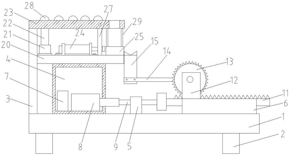
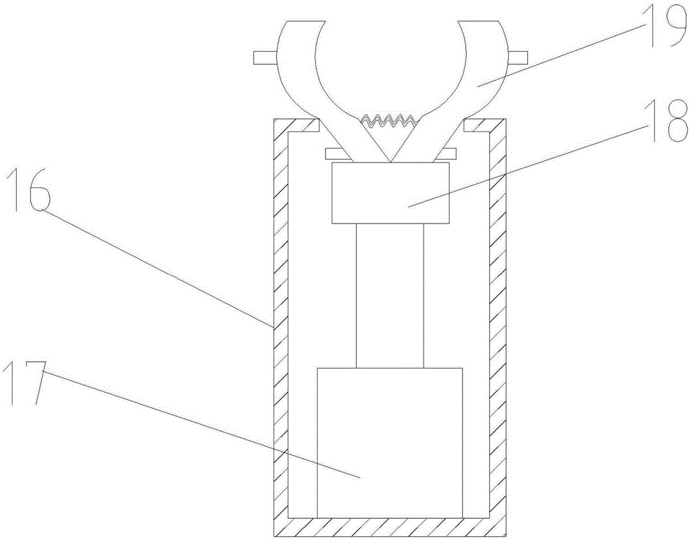
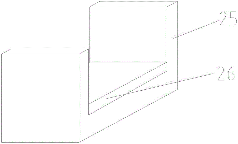
[0038] like figure 1 , figure 2 , image 3 , Figure 4 , Figure 5 , Image 6 , Figure 7 , Figure 8 , Figure 9 , Figure 10 , Figure 11 and Figure 12 As shown in the figure, this embodiment includes a feeding device, a clamping and positioning device, a grinding device and a measuring device. The clamping and positioning device is located at the discharge end of the feeding device, and the grinding device is located above the clamping and positioning device. The measuring device is located at the discharge end of the grinding device.

[0039] The feeding device includes a machine base 1, the bottom of the machine base 1 is installed with a support leg 2, and the upper surface of the machine base 1 is sequentially provided with a pillar 3, a work box 4, a support block 5 and a support base 6 from left to right. , the inner left side of the w...


PUM


Abstract

The invention discloses plastic pipe surface treatment equipment which comprises a feeding device, a clamping and locating device, a grinding device and a measuring device. The clamping and locating device is located at the discharging end of the feeding device. The grinding device is located above the clamping and locating device. The measuring device is located at the discharging end of the grinding device. The automatic feeding purpose is achieved through the feeding device; a material carrying mechanism with the adjusting function is adopted, the structure is simple, operation is convenient, and the adjusting effect is achieved; a lifting device is arranged so that a whole grinding head mechanism can move upwards, downwards, leftwards and rightwards, and the use limitation is avoided; after grinding is finished and through the cooperation of a first clamping device and a second clamping device, a steel pipe can be rotated when clamped and can be measured by the measuring device at multiple angles, and vibration and shakes of the steel pipe are reduced; and a carrying board is arranged, so that the steel pipe is placed more stably and measured more accurately, errors are reduced, and the measuring effect of the steel pipe is better.

Description

technical field [0001] The invention particularly relates to a surface treatment equipment for plastic pipe fittings. Background technique [0002] As an important part of chemical building materials, plastic pipe fittings are widely accepted by users for their superior performance, hygiene, environmental protection, and low consumption. , When the mold is closed and opened, there will be wear and tear, which will produce foreign objects on the surface of the plastic parts. Due to defects such as wire drawing, flash, silver streak caused by defects in materials, injection molding process and abrasive tools, and scratches and other defects caused by demoulding, storage, and re-hanging, these defects need to be surface treated to ensure the surface of the plastic material. It is relatively smooth. In addition, grinding and polishing can improve the surface roughness of the plastic material, which is conducive to the adhesion of paint. At present, the process of surface treat...

Claims


Application Information

Patent Timeline
Patent Type & Authority Applications(China)
IPC IPC(8): B24B41/00B24B41/06B24B49/00B24B29/08B24B5/50
CPCB24B41/005B24B5/50B24B29/08B24B41/067B24B49/00
Inventor 张贤金
Owner CHONGQING XINYONG LIGHTINGS FACTORY
Why Eureka
Try Eureka