Eureka AIR delivers breakthrough ideas for toughest innovation challenges, trusted by R&D personnel around the world.

Robot zero calibration device and robot zero calibration system as well as robot zero calibration method

A zero-point calibration and robot technology, which is applied in the field of robots, can solve problems such as low precision, low efficiency, and inaccurate zero point position, and achieve the effects of improving versatility, simple structure, and improving calibration efficiency and accuracy

Active Publication Date: 2016-03-16
GREE ELECTRIC APPLIANCES INC OF ZHUHAI
View PDF6 Cites 9 Cited by
  • Summary
  • Abstract
  • Description
  • Claims
  • Application Information

AI Technical Summary

Problems solved by technology

The first is to use a three-coordinate measuring instrument or a laser interferometer for coordinate positioning, and then perform zero-point position calibration by calculating a larger amount of calculations on the coordinate equations and calibration equations. The measurement accuracy is high, but the measurement process is cumbersome and efficient. It is not high, and the detection process of different models is different, and the versatility is not high; the second method is to design zero alignment at each joint, and add positioning pins for calibration. This method has low accuracy; the third method uses high-precision The sensor is installed on the robot body, and then the zero point is calibrated. This method is easy to install and design, but the sensor is relatively precise, and errors will be introduced during the installation process, resulting in inaccurate zero point position.

Method used


Image

  • Robot zero calibration device and robot zero calibration system as well as robot zero calibration method
  • Robot zero calibration device and robot zero calibration system as well as robot zero calibration method
  • Robot zero calibration device and robot zero calibration system as well as robot zero calibration method

Examples


Embodiment Construction

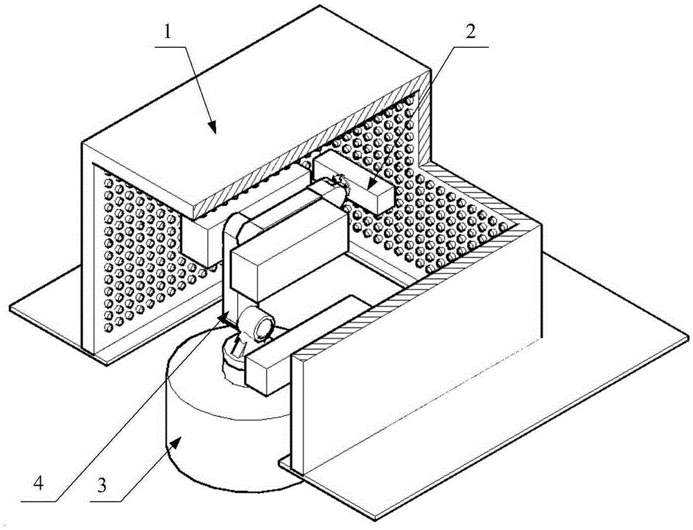
[0041] The invention discloses a robot zero point calibration device, which improves calibration efficiency and precision and has a wide application range. The invention also discloses a robot zero point calibration system and a robot zero point calibration method provided with the robot zero point calibration device.

[0042] The following will clearly and completely describe the technical solutions in the embodiments of the present invention with reference to the accompanying drawings in the embodiments of the present invention. Obviously, the described embodiments are only some, not all, embodiments of the present invention. Based on the embodiments of the present invention, all other embodiments obtained by persons of ordinary skill in the art without making creative efforts belong to the protection scope of the present invention.

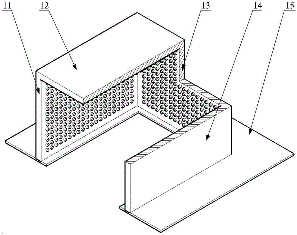
[0043] Please refer to figure 1 with figure 2 , figure 1 Schematic diagram of the structure of the robot zero point calibration system pro...


PUM


Abstract

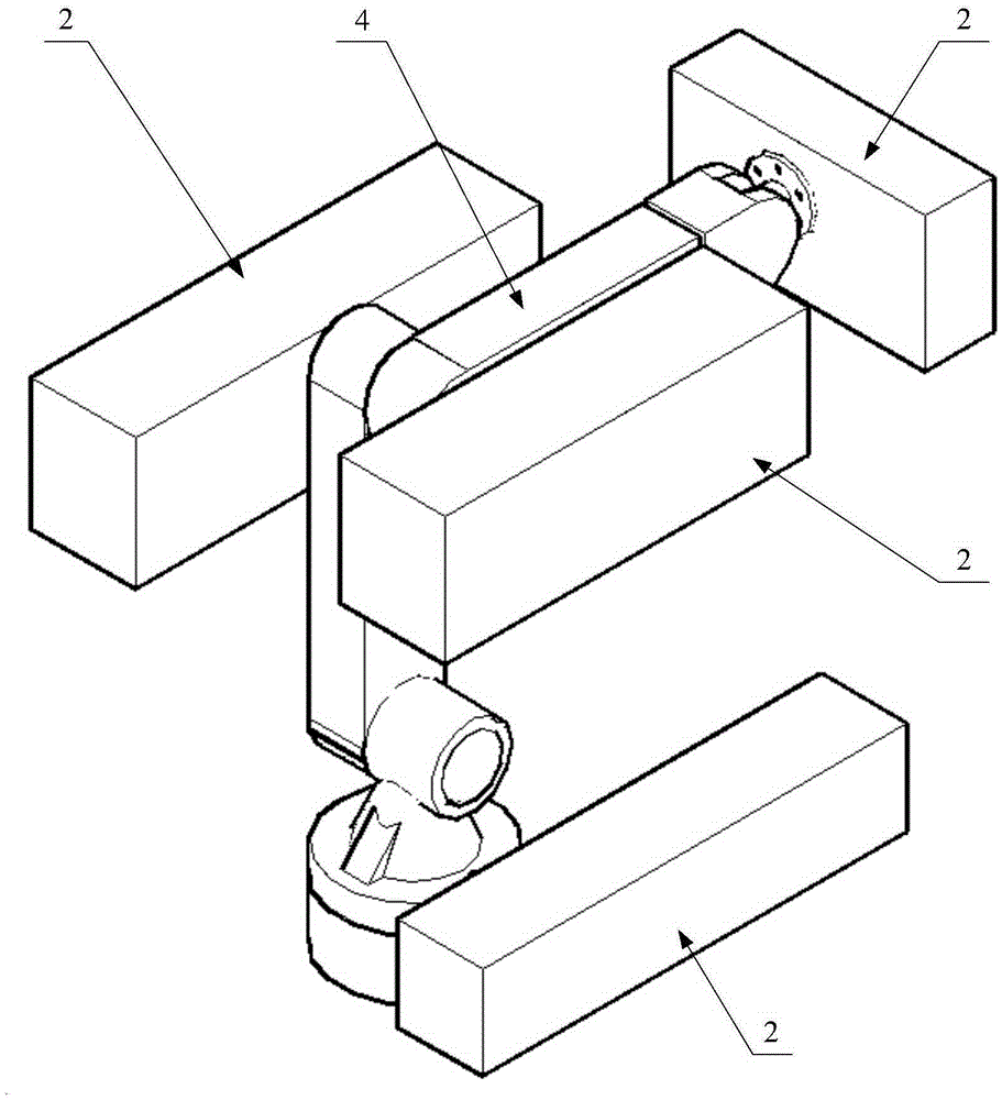
The invention discloses a robot zero calibration device and a robot zero calibration system as well as a robot zero calibration method. The robot zero calibration device comprises a sensing part (1), a locating block (2) and a moving base (3), wherein the sensing part (1) is provided with a sensing cavity and an opening for entry of a robot (4); a position sensor matrix is arranged on the inner side surface of the sensing cavity; the locking block (2) is used for connection with a calibration part of the robot (4) and is detected by the position sensor matrix; and the moving base (3) is used for moving the robot (4) to the interior of the sensing cavity. The robot zero calibration device provided by the invention has the beneficial effects that only one robot needs to be calibrated, the robots of the same model can be automatically calibrated in combination of the sensing part, the locating lock and the moving base, the complication of successive manual calibration is avoided, and the calibration efficiency and accuracy are improved; and the robot zero calibration device is simple in structure and can be used for performing zero location calibration on multiple types of robots, and the universality of the device is improved.

Description

technical field [0001] The invention relates to the technical field of robots, in particular to a robot zero point calibration device, a robot zero point calibration system and a calibration method. Background technique [0002] At present, industrial robots have become a standard equipment and are widely used all over the world. In the practical application of industrial robots, in order to reduce the errors in actual operation, the accuracy of the robot needs to be calibrated and improved by a suitable method or system. [0003] The movement of the mechanical arm of an industrial robot needs to determine the trajectory according to the start coordinates and end coordinates in the three-dimensional space, so as to perform trajectory planning. After trajectory planning, the motion control module is used to control and drive the robot's action implementation module. The position and pose of the object the robot is working on can move the arm to a point in the workspace that...

Claims


Application Information

Patent Timeline
IPC IPC(8): B25J9/10B25J9/16
CPCB25J9/10B25J9/1692
Inventor 王业率赵天光
Owner GREE ELECTRIC APPLIANCES INC OF ZHUHAI
Why Eureka
Eureka Blog
Learn More