An inner anchor head for down-the-hole impact bottom expansion and its use method

An inner anchor head and submerged hole technology, which is applied in the direction of earthwork drilling, installation of anchor rods, sheet pile walls, etc., can solve the problems of narrow application range, low grinding and reaming, etc., and achieve good reaming effect and low environmental requirements , The effect of convenient construction

Active Publication Date: 2017-03-29
WUDA JUCHENG STRUCTURE CO LTD
View PDF1 Cites 0 Cited by
  • Summary
  • Abstract
  • Description
  • Claims
  • Application Information

AI Technical Summary

Problems solved by technology

Although this design uses a conical head and sleeve matching the bottom hole as the inner anchor head, it is still a bottom expansion method of die expansion in essence. Not only the effect of grinding and reaming is low, but also easy Restricted by the bottom expansion environment, the application range is narrow

Method used


Image

  • An inner anchor head for down-the-hole impact bottom expansion and its use method
  • An inner anchor head for down-the-hole impact bottom expansion and its use method
  • An inner anchor head for down-the-hole impact bottom expansion and its use method

Examples


Embodiment 1

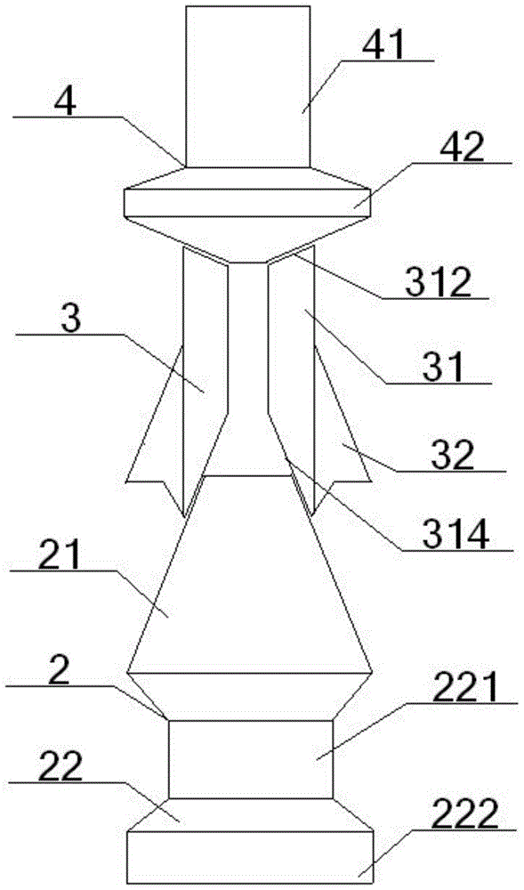
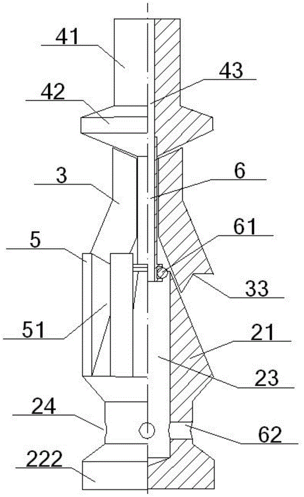
[0061] See figure 1 - Image 6 , A DTH impact expanding bottom inner anchor head, comprising a base 2, a cutter head 3 and a connecting cap 4. The number of the base 2, the connecting cap 4 is one, the number of the cutter head 3 is at least two, and the connecting cap 4. The cutter head 3 and the base 2 are arranged from top to bottom;

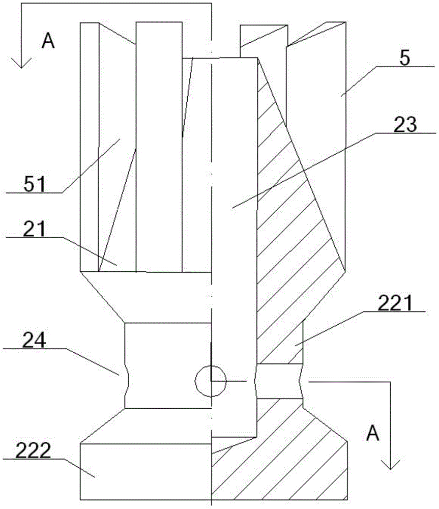
[0062] The base 2 includes a base head 21 and a base tail 22. The base head 21 is a truncated cone structure with a narrow top and a wide bottom. The side surface of the base head 21 is a conical surface or a rhombus cone. The base tail 22 includes The upper tail part 221 and the lower tail part 222, the bottom surface of the base head 21 is connected to the lower tail part 222 after the upper tail part 221, the base head 21 and the upper tail part 221 are provided with the same column-shaped socket 23, the socket The top surface of the base 23 is flush with the top surface of the base head 21, the inner wall of the socket 23 is threaded to conn...

Embodiment 2

[0067] The basic content is the same as Example 1, the difference is:

[0068] A plurality of vertical groove blocks 5 are provided on the side of the base head 21, and a sliding groove 51 corresponding to the cutter head 3 is formed between the adjacent groove blocks 5. The number of the sliding groove 51 and the cutter head 3 is Consistent, the sliding groove 51 is slidingly fitted with the cutter head 3 embedded therein, and the bottom surface of the sliding groove 51 is slidingly fitted with the sliding surface 314 of the cutter head 3 corresponding to the sliding groove 51; the cutter head 3 and the sliding groove 51 The number is 2-18, and the slope of the bottom surface of the chute 51 is 1:1-10:1. The bottom surface of the sliding groove 51 refers to a part of the side surface of the base head 21 in the sliding groove 51. The sliding groove 51 can better position the position of the cutter head 3 during use, and prevent the cutter head 3 from turning over when the connec...

Embodiment 3

[0070] The basic content is the same as Example 1, the difference is:

[0071] The outer corner block 32 is provided with a recessed groove 33 at the junction of the outer plane 313 and the seat sliding surface 314. The groove 33 and the outer corner block 32 form a vertical acute angle 331 and a horizontal acute angle 332. The acute angle 331 is set near the junction of the outer plane 313 and the seat sliding surface 314, and the distance between the horizontal acute angle 332 and the outer plane 313 is the maximum distance between the outer corner block 32 and the outer plane 313.


PUM


Abstract

An inner anchor head for down-the-hole impact expansion, including a connecting cap, a cutter head and a base arranged in sequence from top to bottom. The surface is slidingly matched with the side of the base head of the frustum of cone structure, and a socket is opened in the base to connect the anchor rod body; Temporary connection, then connect the down-the-hole drilling air pressure impactor and connecting rod, and then put them into the straight hole, and the impactor directly impacts the inner anchor head to expand the bottom. After completion, pull out the drill pipe, impactor, and connecting cap, and then Insert the anchor rod body into the socket for connection, and finally inject grout. When expanding the bottom, the debris chiseled by the cutter head can be blown away immediately through the air guide tube. This design is not only suitable for the self-expanding bottom of longer bolts, but also has high energy transfer efficiency and good hole reaming effect, and has low environmental requirements, automatic slag discharge, and high excavation efficiency.

Description

Technical field [0001] The invention belongs to the technical field of construction engineering anchor rod foundation anti-floating, side slope and tunnel engineering anchor rod support, and in particular relates to a down-the-hole impact expansion bottom inner anchor head and its use method, and is particularly suitable for longer anchor rods Self-expanding bottom improves energy transfer efficiency, enhances hole expansion effect, and has low environmental requirements. Background technique [0002] The anchor rod is composed of a rod body, an anchor section, a free section and an anchor head. In order to increase the anchoring effect of the anchoring section of the rock bolt and the anchoring effect of the rock mass, the expansion of the anchoring section is increased by reaming the bottom of the straight hole of the rock, and using the enlarged head at the bottom of the bolt and the reaming to mechanically engage the inner anchor head. The anchoring force improves the cost p...

Claims


Application Information

Patent Timeline
Patent Type & Authority Patents(China)
IPC IPC(8): E02D5/74E21D21/00E21D20/00
CPCE02D5/74E02D2600/30E21D20/00E21D21/00
Inventor 周剑波高作平陈明祥
Owner WUDA JUCHENG STRUCTURE CO LTD
Why Eureka
Try Eureka