Low infrared signature lobe injection mixing device used for two-dimensional nozzle outlet

A binary nozzle and mixing device technology, applied in jet propulsion devices, machines/engines, etc., can solve the problems of limited cold air flow, no ejection channel for cold air flow, limited suppression effect, etc., to reduce resistance, The effect of reducing the intensity of infrared radiation and reducing the temperature

Inactive Publication Date: 2016-03-16
NANJING UNIV OF AERONAUTICS & ASTRONAUTICS
View PDF6 Cites 4 Cited by
  • Summary
  • Abstract
  • Description
  • Claims
  • Application Information

AI Technical Summary

Problems solved by technology

[0006] Judging from the existing literature, the main profile characteristics of the current traditional binary injection nozzles (such as long casing binary injection nozzles, short casing binary injection nozzles, etc.) are The outlet is covered with a binary cylinder with a slightly larger equivalent diameter. The binary injection nozzle obtained in this way has very limited enhancement of the shielding effect on the high-temperature parts inside the nozzl

Method used


Image

  • Low infrared signature lobe injection mixing device used for two-dimensional nozzle outlet
  • Low infrared signature lobe injection mixing device used for two-dimensional nozzle outlet
  • Low infrared signature lobe injection mixing device used for two-dimensional nozzle outlet

Examples


Embodiment 1

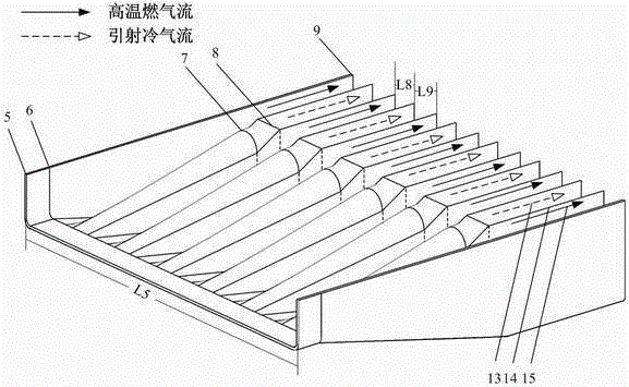
[0044] Set the logarithm n of the outer expansion lobe to 6, then the logarithm of the inner expansion lobe is 5; the logarithm n of the outer expansion lobe is 1.5 times the aspect ratio, then the aspect ratio AR is 4, and the width L5 Take 1.44m; then the inlet equivalent diameter of the rectangular transition section 1 is taken as 0.576, and the area A1 of the inlet section 5 is 0.5184m 2 .

[0045] The area A2 of the outlet section 7 of the lobe section 2 is equal to the inlet area of ​​the rectangular transition section, which is also 0.5184m 2 , the area A3 of the outlet section 8 of the lobe transition section 3 is twice the entrance area of ​​the rectangular transition section, that is, 1.0368m 2 , the area A4 of the outlet section 9 of the split cold and hot flow passage section 4 is equal to it.

[0046] In terms of length, the axial length L1 of the rectangular transition section 1 is 0.1 times the equivalent diameter of the inlet of the rectangular transition sec...

Embodiment 2

[0048] Set the logarithm n of the outer expansion lobe to 12 pairs, then the logarithm of the inner expansion lobe is 11; the inlet equivalent diameter of the rectangular transition section 1 is 0.576, the aspect ratio AR is 4, and the width L5 is 1.44m.

[0049] According to the above data, the area A1 of the entrance section 5 is 0.5184m 2 , the area A2 of the outlet section 7 of the lobe section 2 is the same as it is 0.5184m 2 , the area A3 of the outlet section 8 of the lobe transition section 3 is 1.0368m 2 , take 1.0368m for the area A4 of the outlet section 9 of the split cold and hot flow channel section 4 2 .

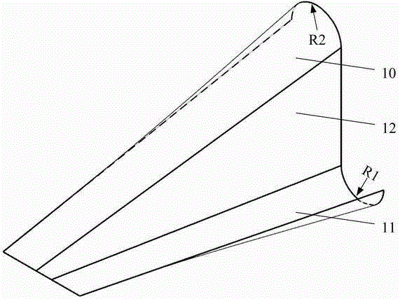
[0050] In terms of length, the axial length L1 of the rectangular transition section 1 is 0.144m, the axial length L2 of the lobe section 2 is 0.6912m, the axial length L3 of the lobe transition section 3 is 0.1152m, and the split cold and hot flow channel section 4 The axial length L4 is 0.3456m, the radius R1 at the end of the outer expansion lobe 11 is 0...

Embodiment 3

[0052] Set the logarithm n of the outer expansion lobes to 9 pairs, then the logarithm of the inner expansion lobes is 8; the equivalent diameter of the entrance of the rectangular transition section 1 is 0.576, and the area A1 of the entrance section 5 is 0.5184m 2 , the aspect ratio AR is 4, and the width L5 is 1.44m.

[0053] The area A2 of the outlet section 7 of the lobe section 2 is taken as 0.5184m 2 , take 1.0368m for the area A3 of the outlet section 8 of the lobe transition section 3 2 , take 1.0368m for the area A4 of the outlet section 9 of the split cold and hot flow channel section 4 2 .

[0054] The axial length L1 of the rectangular transition section 1 is taken as 0.103m, the axial length L2 of the lobe section 2 is taken as 0.5042m, the axial length L3 of the lobe transition section 3 is taken as 0.0808m, and the axial length L4 of the split cold and hot flow channel section 4 is taken as 0.2882m, the radius R1 at the end of the outer expansion lobe 11 is ...


PUM


Abstract

The invention provides a low infrared signature lobe injection mixing device used for a two-dimensional nozzle outlet. The low infrared signature lobe injection mixing device comprises a rectangular transition section, lobe sections, lobe transition sections and separated cold and hot flow channel sections. A traditional two-dimensional nozzle molded surface cannot effectively shield inner high temperature parts (a center cone, a support plate and a mixer) of an exhaust system, while the special lobe molded surface and baffle plates in separated cold and hot flow channels of the device can effectively shield the high temperature parts, and the detectable infrared radiation of the high temperature parts is reduced; the separated cold and hot flow channel sections separate high temperature combustion-gas flow from injected cold air flow, so that the resistance of cold air flow injection is effectively decreased, and the injection quantity of cold air flow is guaranteed to be quite considerable; and besides, cold flow and hot flow are mixed at the outlet of the device, so that the temperature of the jet flow is greatly decreased, and the infrared radiation of the jet flow can be reduced.

Description

technical field [0001] The patent of the present invention relates to the technical field of suppression of infrared radiation characteristics of aircraft, specifically, it mainly relates to a low-infrared characteristic lobe ejection mixing device for binary nozzle outlets. Background technique [0002] Under the threat of the current complex electromagnetic search and detection environment and advanced ground-to-air and air-to-air weapons and equipment, the battlefield survival environment of aircraft is deteriorating day by day. How to improve the survivability of aircraft on the battlefield and implement effective attacks against the enemy has become one of the key technologies that modern warfare urgently needs to develop. According to statistics, in several air battles since the 1980s, aircraft shot down by infrared guided missiles accounted for 70-80% of the total number of aircraft shot down in the war. Mainly the threat of third-generation infrared air-to-air missi...

Claims


Application Information

Patent Timeline
IPC IPC(8): F02K1/38F02K1/46
Inventor 吉洪湖王丁黄伟
Owner NANJING UNIV OF AERONAUTICS & ASTRONAUTICS
Why Eureka
Try Eureka