Dynamic braking device of crane

A braking device and crane technology, applied in mechanical equipment, drum brakes, brake types, etc., can solve the problems of aggravating the load of the traveling gearbox, affecting the production progress, dangerous product loading and unloading, etc., to achieve good braking performance, safe and convenient loading and unloading. Effect

Inactive Publication Date: 2016-03-16
ZHEJIANG TOHIGH BUILDING MATERIALS GROUP
View PDF4 Cites 2 Cited by
  • Summary
  • Abstract
  • Description
  • Claims
  • Application Information

AI Technical Summary

Problems solved by technology

This way of working is very dangerous for cranes to hoist products. The general walking speed of cranes reaches 60-80 m/min (some cranes are as slow as 20-30 m/min), and the control method is motor failure. Electricity, the brakes hold the brakes tightly, and the objects hoisted by the crane shake due to inertia, which poses a great danger to product loading and unloading
In order to reduce

Method used


Image

  • Dynamic braking device of crane
  • Dynamic braking device of crane

Examples


Embodiment Construction

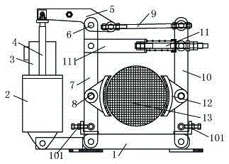
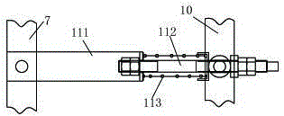
[0013] Combine below figure 1 and figure 2 Specific description embodiment:

[0014] Such as figure 1 and figure 2 As shown, the dynamic braking device of the crane includes a base plate 1 and an oil pump 2, the oil pump 2 is connected with an oil pump motor 3 and an oil pump ejector rod 4, and the end of the oil pump ejector rod 4 is connected with one end of a working block 5, The working block 5 is hingedly connected to the second bracket 7 through the pin shaft 6. The working block 5 can rotate around the pin shaft 6 under the action of the oil pump ejector rod 4. The other end of the second bracket 7 is arranged on the bottom plate 1. The second bracket 7 is provided with a second brake pad assembly 8; the other end of the working block 5 is connected with a jack screw 9, and the jack screw 9 is connected to the first bracket 10, and the first bracket 10 The other end is arranged on the base plate 1, the first bracket 10 and the second bracket 7 are respectively arr...


PUM


Abstract

The invention belongs to the technical field of crane tools, and particularly relates to a dynamic braking device of a crane. The dynamic braking device of the crane comprises a bottom plate and an oil pump. The oil pump is connected with an oil pump motor and an oil pump ejector rod. The end of the oil pump ejector rod is connected with one end of a work block. The work block is connected to a second support through a pin shaft in a hinged manner. The work block can rotate with the pin shaft as the center through the oil pump ejector rod. Then, a first brake pad combination and a second brake pad combination can approach a brake disc at the same time to finish dynamic braking. The dynamic braking device has the beneficial effects that walking of the crane can be dynamically controlled, the damage to the motor and a transmission of the crane due to reverse braking for shutdown of the crane is reduced, the crane can slowly shut down, objects hoisted by the crane cannot swing even when inertia exists, and loading and unloading safety is greatly facilitated.

Description

technical field [0001] The invention belongs to the technical field of crane appliances, in particular to a dynamic braking device for a crane. Background technique [0002] The traveling mechanism of the crane is basically equipped with a static brake device. The control of the brake device is connected with the control of the motor. The motor starts the brake and opens, and the motor loses power and the brake is held tightly by the spring. This way of working is very dangerous for cranes to hoist products. The general walking speed of cranes reaches 60-80 m / min (some cranes are as slow as 20-30 m / min), and the control method is motor failure. Electricity, the brakes hold the brakes tightly, and the objects hoisted by the crane shake due to inertia, which poses a great danger to product loading and unloading. In order to reduce the occurrence of danger, in actual work, the brake is loosened to make it work ineffective. The traveling brake of the crane is completely realize...

Claims


Application Information

Patent Timeline
IPC IPC(8): F16D49/16F16D65/18B66C13/06F16D121/02
CPCF16D49/16B66C13/06F16D65/18F16D2121/02F16D2131/00
Inventor 周浩
Owner ZHEJIANG TOHIGH BUILDING MATERIALS GROUP
Why Eureka
Try Eureka