
Chip charging barrel for steel casting electric furnace

A technology for feeding barrels and electric furnaces, which is applied to furnaces, furnace components, charge control and other directions, can solve the problems of reduced economic benefits, increased costs, complex structures, etc., and achieves the effects of increased economic benefits, easy feeding, and simple structure.

Inactive Publication Date: 2016-03-16
CHONGQING YUXI STEEL GRP CO LTD
View PDF0 Cites 0 Cited by
  • Summary
  • Abstract
  • Description
  • Claims
  • Application Information

AI Technical Summary

Problems solved by technology

[0005] In order to overcome the disadvantages of the existing charging device for steel electric furnace, such as complex structure, difficulty in controlling the amount of feeding, and inability to realize automatic feeding, resulting in increased cost and reduced economic benefit, the technical problem to be solved by the present invention is to provide a simple structure, And it is easy to control the feeding amount, which reduces the cost and improves the economic benefit, and can realize the automatic feeding of iron and steel electric furnace iron scrap feeding barrel

Method used


Image

  • Chip charging barrel for steel casting electric furnace
  • Chip charging barrel for steel casting electric furnace
  • Chip charging barrel for steel casting electric furnace

Examples


Embodiment 1

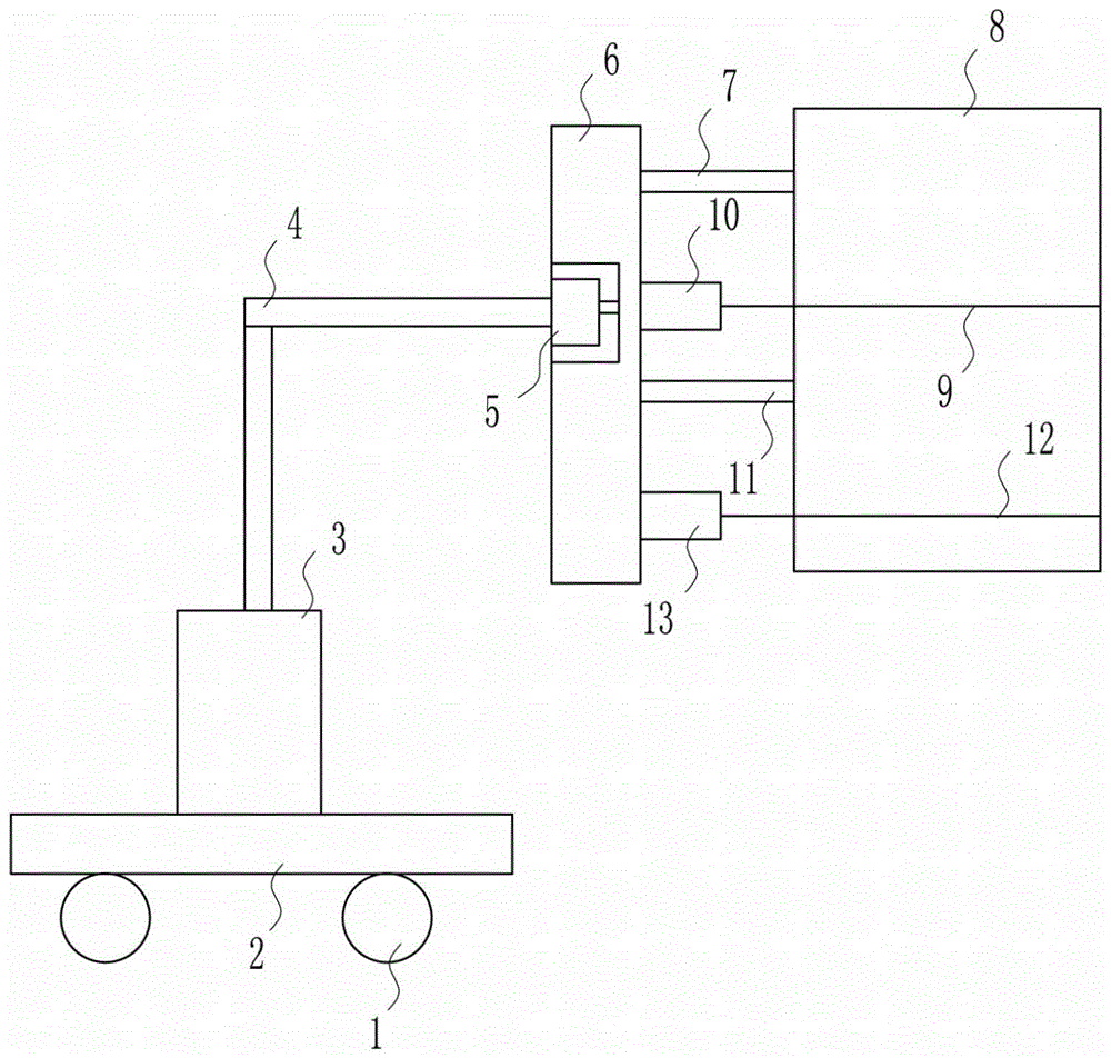
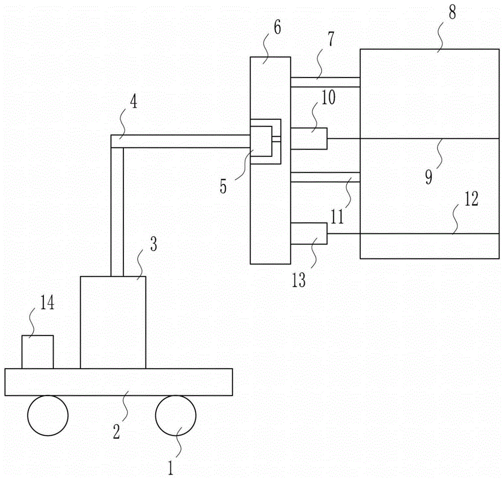
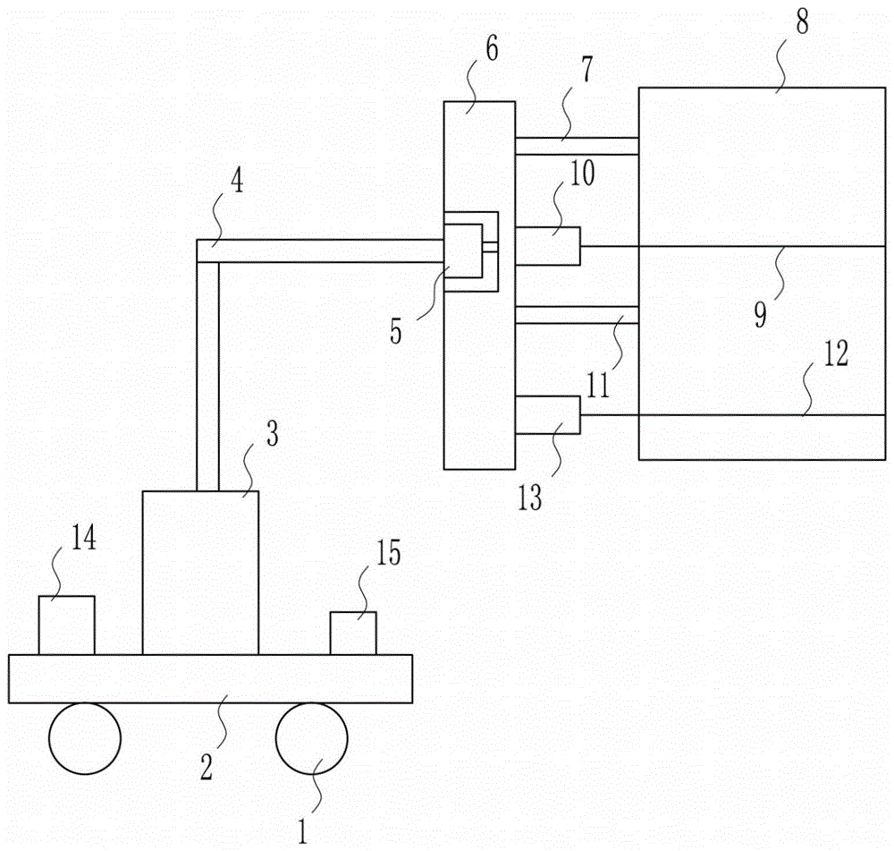
[0021] A kind of iron and steel electric furnace scrap feeding barrel, such as Figure 1-3 As shown, it includes wheel 1, plate Ⅰ2, cylinder 3, connecting rod Ⅰ4, motor 5, plate Ⅱ6, connecting rod Ⅱ7, feeding barrel 8, baffle Ⅱ6, electric push rod Ⅱ10, connecting rod Ⅲ11, baffle Ⅰ2 and electric Push rod Ⅰ13; wheel 1 is set at the bottom of plate Ⅰ2, cylinder 3 is set in the middle of the top of plate Ⅰ2, connecting rod Ⅰ4 is connected above cylinder 3, plate Ⅱ6 is set on the right side of connecting rod Ⅰ4, and motor 5 is embedded in plate Ⅱ6 Inside, the right side of the plate II6 is provided with connecting rod II7, electric push rod II10, connecting rod III11 and electric push rod I13 from top to bottom, and the right side of connecting rod II7 and connecting rod III11 is connected with a feeding barrel 8, electric The right side of the push rod I13 is connected with the baffle plate I2, and the right side of the electric push rod II10 is connected with the baffle plate II6...


PUM


Abstract

The invention relates to a charging barrel, in particular to a chip charging barrel for a steel casting electric furnace. The technical problem to be solved by the invention is to provide the chip charging barrel simple in structure, easy to control the charging quantity, reducing the cost, increasing the economic benefit and capable of realizing automatic charging. In order to solve the technical problem, the invention provides the chip charging barrel for the steel casting electric furnace; the chip charging barrel comprises wheels, a plate I, a cylinder, a connecting rod I, a motor, a plate II, a connecting rod II, a charging barrel, a baffle plate II, an electric push rod II, a connecting rod III, a baffle plate I and an electric push rod I; the wheels are arranged at the bottom of the plate I; the cylinder is arranged in the middle of the top of the plate I; the connecting rod I is connected above the cylinder; the plate II is arranged at the right side of the connecting rod I; and the motor is inlaid in the plate II. The chip charging barrel overcomes the defects of complex structure, difficult control of the charging quantity, incapability of realizing automatic charging, high cost and low economic benefit of a traditional charging device for the steel casting electric furnace.

Description

technical field [0001] The invention relates to a charging barrel, in particular to a charging barrel for iron and steel electric furnace scrap. Background technique [0002] The electric furnace is a heating furnace that converts the electric energy in the furnace into heat to heat the workpiece. Compared with the fuel furnace, the advantages of the electric furnace are: the atmosphere in the furnace is easy to control; the material is heated quickly; the heating temperature is high; the temperature is easy to control, etc. [0003] The existing steel electric furnace feeding device has a complex structure, and it is difficult to control the feeding amount, and it is impossible to realize automatic feeding, resulting in higher costs and lower economic benefits. The benefit is increased, which can realize the automatic feeding of iron and steel electric furnace iron filings feeding barrel. Contents of the invention [0004] (1) Technical problems to be solved [0005] In...

Claims


Application Information

Patent Timeline
IPC IPC(8): F27D3/00
Inventor 周木火
Owner CHONGQING YUXI STEEL GRP CO LTD
Learn More