Method for controlling temperature of photoelectric separate fiber optic gyroscope optical path

A fiber optic gyroscope, photoelectric separation technology, applied in Sagnac effect gyroscope, gyroscope/steering sensing device, temperature control and other directions, can solve the difficulty of fiber optic gyroscope temperature compensation model, unfavorable gyroscope engineering, difficult gyroscope Drift precision compensation and other issues, to achieve the effect of reducing gyro output drift, easy structural improvement, and low cost

Active Publication Date: 2016-03-16
BEIJING AEROSPACE TIMES OPTICAL ELECTRONICS TECH
View PDF5 Cites 17 Cited by
  • Summary
  • Abstract
  • Description
  • Claims
  • Application Information

AI Technical Summary

Problems solved by technology

However, due to the uncertainty of environmental changes, it is difficult to establish a fiber optic gyroscope temperature compensation model, which is easily affected by many other factors such as test conditions and equipment status, and it is difficult to achieve accura

Method used


Image

  • Method for controlling temperature of photoelectric separate fiber optic gyroscope optical path
  • Method for controlling temperature of photoelectric separate fiber optic gyroscope optical path
  • Method for controlling temperature of photoelectric separate fiber optic gyroscope optical path

Examples


Embodiment Construction

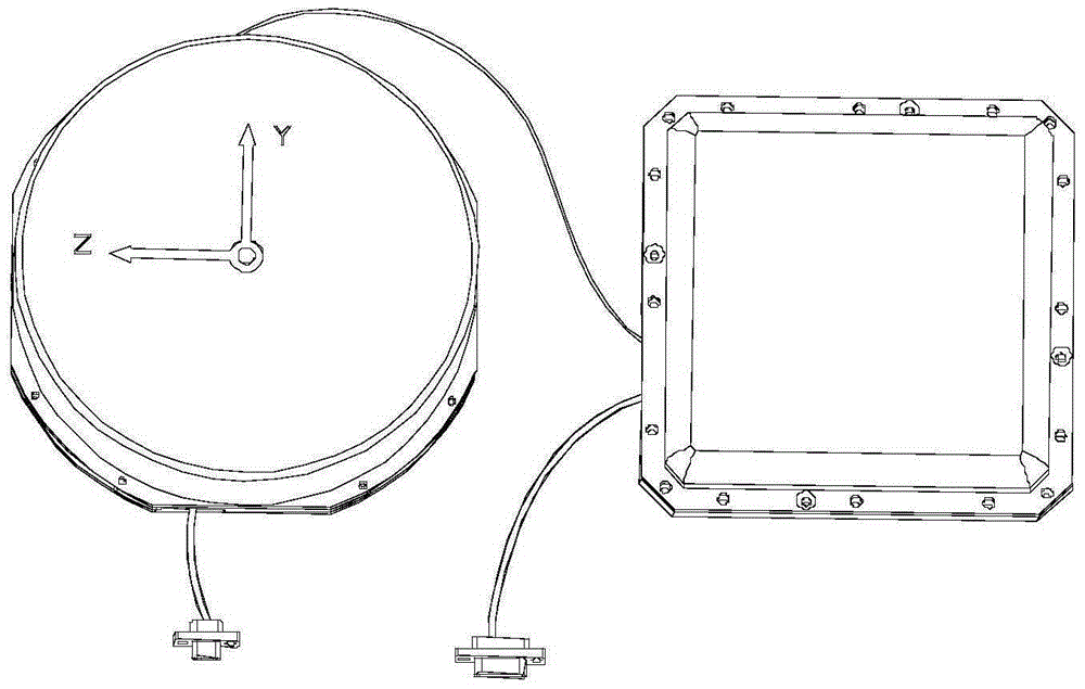
[0036] The temperature control method of the present invention is used in photoelectric separation fiber optic gyroscopes, such as figure 1 As shown, heat-generating components such as circuit boards, detectors, and light sources are installed in the square circuit box structure, and temperature-sensitive devices such as fiber optic ring 3 are assembled in the circular optical path structure. Through structural improvement in the optical path, the sensitivity to angular velocity in the optical path The key component of the system is the fiber optic ring for temperature control.

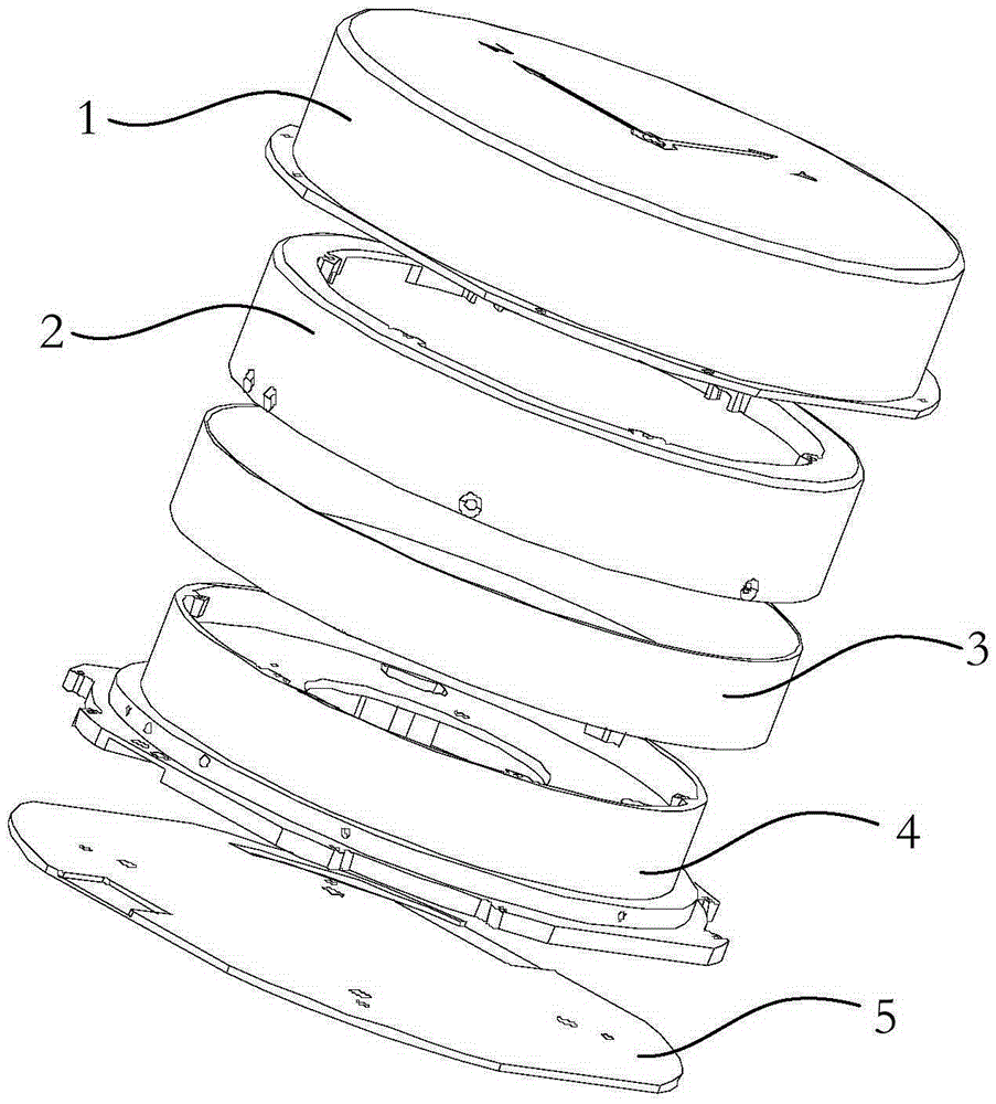
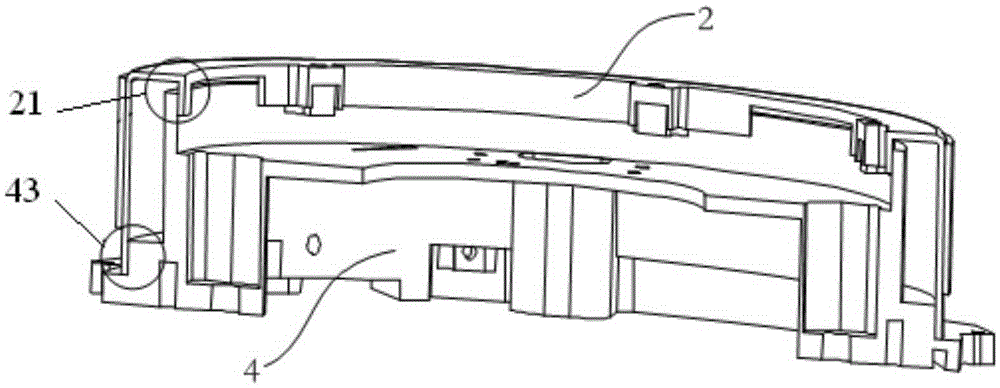
[0037] Such as figure 2 As shown, the optical fiber ring 3 is wound on the cylindrical structure of the optical fiber ring skeleton 4, the optical fiber ring skeleton 4 is installed on the base 5, and the magnetic shielding outer cover 2 is set outside the cylindrical structure of the optical fiber ring skeleton 4, so that the magnetic shielding outer cover 2 An airtight magnetic shielding space is ...


PUM

PropertyMeasurementUnit
Diameteraaaaaaaaaa
Depthaaaaaaaaaa

Abstract

The invention discloses a method for controlling temperature of a photoelectric separate fiber optic gyroscope optical path, which comprises steps: a magnetic shielding outer cover (2) is arranged on an optical fiber ring skeleton (4), and forms a closed magnetic shielding space with the optical fiber ring skeleton (4), the magnetic shielding outer cover (2) uses a covered edge design, and is clung to the upper edge of the optical fiber ring skeleton (4) after being mounted, and is packed on the inner wall of the optical fiber ring skeleton (4) along the peripheral direction, electrical heating bands are pasted on the optical fiber ring skeleton (4), and heat is transmitted to the optical fiber ring skeleton (4) through the magnetic shielding outer cover (2), and is transmitted to an optical fiber ring (3) through the optical fiber ring skeleton (4), thereby enabling the optical fiber ring (3) to achieve temperature balance. The method for controlling temperature of the photoelectric separate fiber optic gyroscope optical path enables the temperature in the optical fiber ring (3) to be uniformly distributed, a gyroscope works in a sett temperature range, prevents bias drift which is produced by shupe in effect, and achieves the performance demands of high precision optical fiber gyroscope zero bias and scale factors.

Description

technical field [0001] The invention relates to a temperature control method for the optical path of a photoelectric separation type fiber optic gyroscope. Background technique [0002] The fiber optic gyroscope is an all-solid-state inertial instrument based on the Sagnac effect, which is used to measure the angular rate of the carrier and is the core component of the inertial system. [0003] As an opto-mechanical-electrical integration sensor, the influence of temperature on the performance of fiber optic gyroscopes cannot be ignored. Temperature has become one of the problems faced by fiber optic gyroscopes towards engineering, and more and more attention has been paid to the temperature performance. As the optical fiber coil of the sensitive element, because the external temperature changes with time, the refractive index of each point of the optical fiber coil changes with the temperature change, and the time for the two beams of light waves propagating in opposite dir...

Claims


Application Information

Patent Timeline
IPC IPC(8): G01C19/72G05D23/24
CPCG01C19/72G01C19/721G01C19/726G05D23/24
Inventor 黄鑫岩高峰闾晓琴朱士群杨建华王冠颖王宁
Owner BEIJING AEROSPACE TIMES OPTICAL ELECTRONICS TECH
Why Eureka
Try Eureka