Fluorescence Imaging Autofocus Systems And Methods

An optical imaging system, fluorescence imaging technology, applied in fluorescence/phosphorescence, optics, optical components, etc., can solve problems such as increasing complexity, slowing down the process, and not providing signals, and achieving the effect of overcoming difficulties and defects

Inactive Publication Date: 2016-03-16
立科有限公司
View PDF6 Cites 13 Cited by
  • Summary
  • Abstract
  • Description
  • Claims
  • Application Information

AI Technical Summary

Problems solved by technology

This further adds complexity and slows down the process
[0006] Furthermore, Olson's technique does not provide a detected signal that exits the detector due to changes in the z-height of the sample
Therefore, the idea of ​​obtaining images at different heights does not work because, at many z-heights, there will be no signal for detection (leaving the detector) and therefore any contrast-based scheme will not be able to detect optimal focus where are you

Method used


Image

  • Fluorescence Imaging Autofocus Systems And Methods
  • Fluorescence Imaging Autofocus Systems And Methods
  • Fluorescence Imaging Autofocus Systems And Methods

Examples


Embodiment Construction

[0026] For imaging in fluorescence, an object (e.g., containing a fluorescent material) is illuminated with an optical signal (excitation light) of a first spectral content, wherein a portion of this signal is absorbed by at least a portion of the object and is emitted as an optical signal of a second spectral content (emission light). light) to re-emit. The emitted light is then detected by a detection system as a measure of the amount of presence of the object at that location. Imaging a fluorescently labeled region therefore requires excitation light delivered to the region of interest, an imaging system that collects the light from the region of interest and projects it onto an optical detector (e.g., a detector array), and an imaging system for imaging the emitted fluorescent light. A device that is separated from the portion of the excitation light that passes through the imaging system. Devices for separation typically include one or more interference filters.

[0027...


PUM


Abstract

Quantitative fluorescence imaging systems and methods using angular illumination to obtain automatic focus information. Laser scanning (e.g., point or line scanning) with angular illumination in combination with an area imaging sensor, such as with a bi-telecentric scanner, is used to determine sample height (relative to a detection axis orthogonal to a platform holding the sample) and also correct for sample height in subsequent scans.

Description

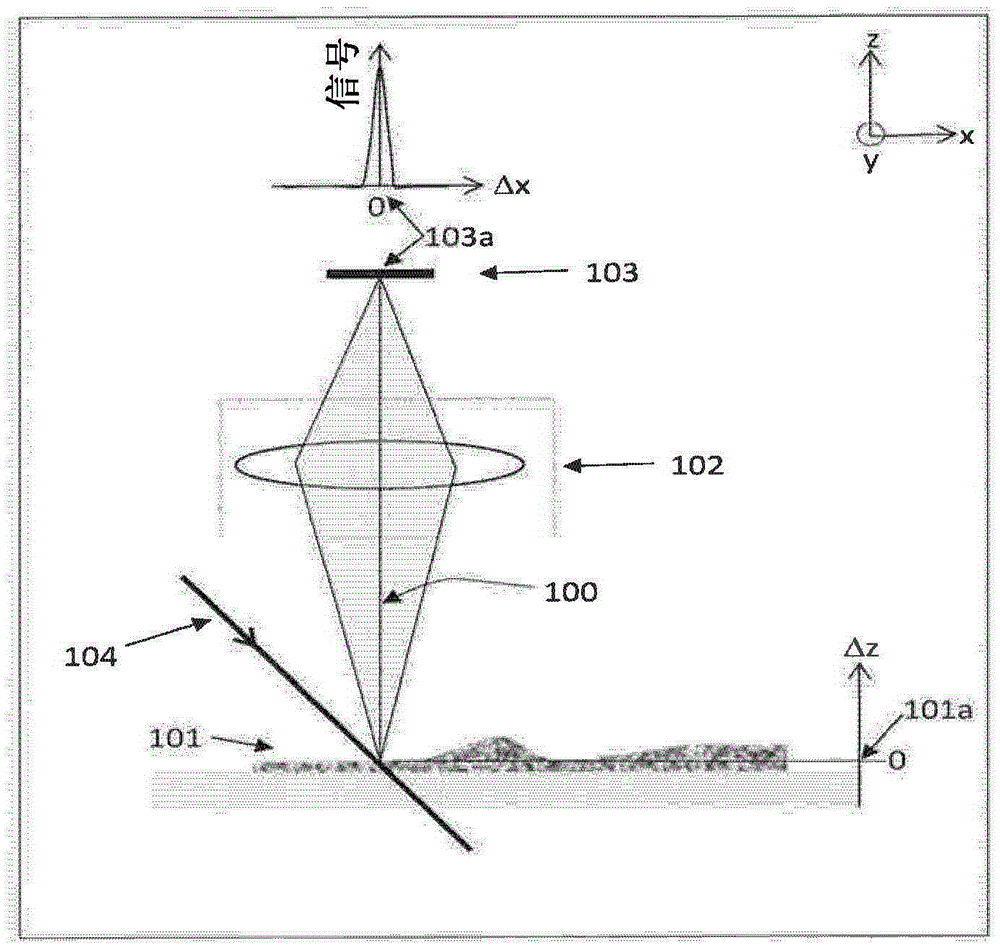
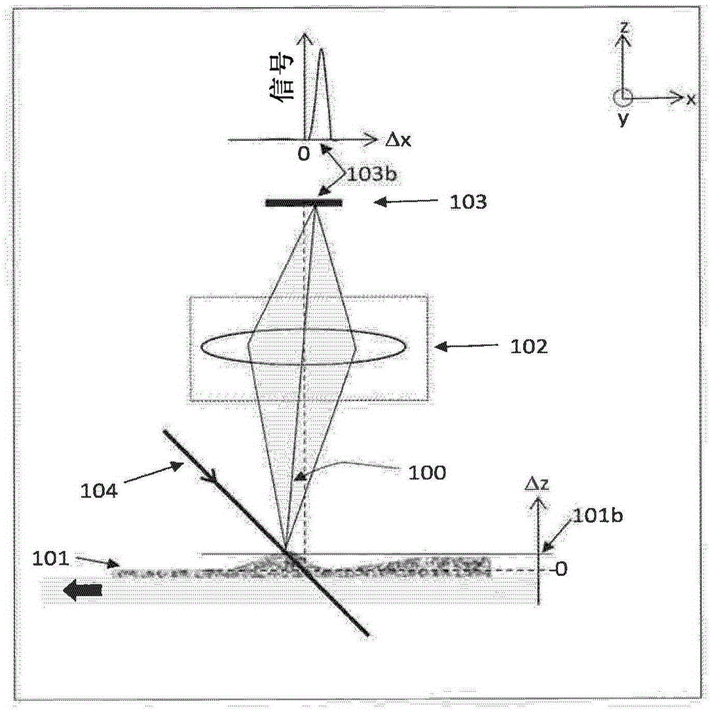
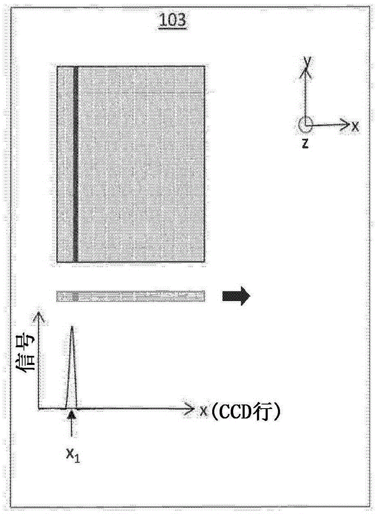
technical field [0001] The present disclosure relates to quantitative fluorescence imaging, and more particularly to autofocus systems and methods using angular illumination. Background technique [0002] A recent improvement in fluorescence imaging is the bi-telecentric widefield fluorescence scanner, which enables accurate quantitative measurements with focus-independent pass-to-pass registration. U.S. Patent Application S / N14 / 312,409, entitled "Telecentric, Wide-Field Fluorescence Scanning Systems and Methods," filed June 23, 2014, which is incorporated herein by reference for all purposes, discusses dual Features of the telecentric wide-field fluorescence scanning system. One feature of this design is angular illumination (excitation), which has the benefit of reduced optical background and thus higher sensitivity. However, a disadvantage of corner illumination is that as the height of the sample changes, so does the position of the imaged line on the sensor. Therefor...

Claims


Application Information

Patent Timeline
Patent Type & Authority Applications(China)
IPC IPC(8): G01N21/64G01N21/01G02B21/00
CPCG01B11/0608G01N21/6456G02B21/082G02B21/244G02B21/26G02B21/367G01N21/6458G02B13/22G02B21/16G01N2021/6463G01N2201/06113G01N2201/1053G02B17/0605G02B21/361
Inventor 艾哈迈德·布齐德克里斯·奥莱夏克
Owner 立科有限公司
Why Eureka
Try Eureka