High-voltage resistant composite membrane ceramic coating of lithium ion battery, composite membrane composed of same, and preparation method and application of composite membrane

A technology for lithium-ion batteries and composite diaphragms, which is applied to battery pack parts, circuits, electrical components, etc., can solve the problems of inability to meet the needs of high-voltage lithium-ion batteries, poor interface stability of ceramic composite diaphragm coatings, and high-voltage stability To improve interface stability, improve cycle performance and safety performance, and reduce side reactions

Active Publication Date: 2016-03-16
QINGDAO INST OF BIOENERGY & BIOPROCESS TECH CHINESE ACADEMY OF SCI
View PDF4 Cites 13 Cited by
  • Summary
  • Abstract
  • Description
  • Claims
  • Application Information

AI Technical Summary

Problems solved by technology

Conventional ceramic coating binders, such as polyvinylidene fluoride (PVDF) or polyvinylidene fluoride-hexafluoropropylene (PVDF-HFP) have poor high-voltage stability, and the prepared ceramic composite diaphragm coating has poor interface stability and Coulomb The efficiency is too low to meet the needs of high-voltage lithium-ion batteries

Method used


Image

  • High-voltage resistant composite membrane ceramic coating of lithium ion battery, composite membrane composed of same, and preparation method and application of composite membrane

Examples


Embodiment 1

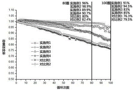
[0022] First, mix the silica ceramic powder with a diameter of 0.5 microns, nitrogen nitrogen dimethylacetamide solvent, and polystyrene carbonate binder in a ratio of 1 gram: 10 grams: 1 gram to obtain a coating slurry material; then, the obtained slurry is coated on both sides of the polypropylene single-layer diaphragm by roller coating, and after heating and drying, a ceramic composite diaphragm with a coating thickness of 10 microns is obtained; finally, the high-voltage lithium ion Test the cycle performance of the separator in the battery;

Embodiment 2

[0024] First, mix the alumina ceramic powder with a diameter of 0.5 microns, nitrogen methyl pyrrolidone solvent, and polybutene succinate binder in a ratio of 1 gram: 10 gram: 1 gram to obtain a coating slurry ; Then, the obtained slurry is coated on both sides of the polypropylene single-layer diaphragm by dip coating, and after heating and drying, a ceramic composite diaphragm with a coating thickness of 15 microns is obtained; finally, in the high-voltage lithium-ion battery Test the cycle performance of the diaphragm;

Embodiment 3

[0026] First, mix titanium dioxide ceramic powder with a diameter of 0.2 microns, nitrogen-nitrogen-dimethylformamide solvent, and polyethylene carbonate binder in a ratio of 1 g: 10 g: 1 g to obtain a coating slurry Then, the obtained slurry is coated on one side of the polypropylene single-layer diaphragm by spraying, and after heating and drying, a ceramic composite diaphragm with a coating thickness of 5 microns is obtained; finally, in the high-voltage lithium-ion battery Test the cycle performance of the diaphragm;


PUM

PropertyMeasurementUnit
diameteraaaaaaaaaa
thicknessaaaaaaaaaa
diameteraaaaaaaaaa

Abstract

The invention relates to a ceramic coating, in particular to a high-voltage resistant composite membrane ceramic coating of a lithium ion battery, a composite membrane composed of the same, and a preparation method and application of the composite membrane. The ceramic coating is composed of a novel high-voltage resistant binding agent and inorganic ceramic powder, wherein the novel high-voltage resistant binding agent comprises at least one of polypropylene carbonate, poly ethylene carbonate, polybutylene succinate, poly cyclohexene carbonate and polystyrene carbonate. The composite membrane with a specified coating thickness is obtained by uniformly mixing the inorganic ceramic powder, an organic solvent and the novel high-voltage resistant binding agent to obtain a coating paste and then applying the obtained paste on a support substrate. The composite membrane can be applied to all high-voltage lithium ion batteries with upper-limit cut-off voltage of 4.4-5.2V. With the composite membrane ceramic coating, the interface stability of the composite membrane can be improved, side reaction is reduced, the coulombic efficiency is improved, and thus, the cycle performance and the safety performance of the high-voltage lithium ion battery can be significantly improved.

Description

technical field [0001] The invention belongs to the technical field of lithium-ion battery diaphragms, and in particular relates to a high-voltage-resistant lithium-ion battery composite diaphragm ceramic coating, a composite diaphragm composed of the same, a preparation method and an application thereof. Background technique [0002] Lithium-ion batteries have been widely used in small electronic digital products and other fields because of their advantages such as high energy density, long life, wide operating temperature window, high safety, environmental friendliness, and no memory effect. However, with the development of large-scale energy storage base stations, electric vehicles and other fields, higher requirements have been placed on the energy density and power density of lithium-ion batteries, and the problem of insufficient battery life of current lithium-ion batteries has become increasingly prominent. Therefore, improving the energy density and power density of ...

Claims


Application Information

Patent Timeline
Patent Type & Authority Applications(China)
IPC IPC(8): H01M2/16H01M2/14H01M50/403H01M50/434H01M50/446H01M50/489
CPCH01M50/403H01M50/446H01M50/449Y02E60/10
Inventor 崔光磊许高洁丁国梁张建军赵江辉
Owner QINGDAO INST OF BIOENERGY & BIOPROCESS TECH CHINESE ACADEMY OF SCI
Why Eureka
Try Eureka