
Control chip for realizing low-standby power consumption of AC-DC switch power supply

A switching power supply and control chip technology, applied in output power conversion devices, electrical components, high-efficiency power electronic conversion, etc., can solve the problems of low standby power consumption, rapid decline, and the chip cannot immediately turn on the primary side.

Active Publication Date: 2016-03-16
ZHEJIANG UNIV +1
View PDF5 Cites 10 Cited by
  • Summary
  • Abstract
  • Description
  • Claims
  • Application Information

AI Technical Summary

Problems solved by technology

But F min It will also have a great impact on the dynamic characteristics of the system. When the load suddenly jumps from no load to full load, it will be affected by F min limit, the chip cannot immediately turn on the primary side to replenish energy, but must wait for the maximum off time T max (T max =1 / F min ) to make the primary side conduction, so that at T max During this period of time, due to the large load on the output terminal and no energy transmission, the output voltage will drop rapidly, and its drop value depends entirely on T max ,T max The larger, that is, F min The lower the power consumption is, the smaller the standby power consumption is, but the worse the dynamic characteristics are, so when certain dynamic characteristics are satisfied, F min can not be lowered
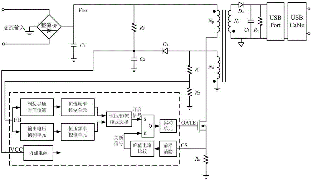
[0009] It can be seen that, limited by the current level of control technology development and the structural limitations of the primary-side control converter, it is difficult to reduce the standby power consumption of the power stage circuit except the control chip.

Method used


Image

  • Control chip for realizing low-standby power consumption of AC-DC switch power supply
  • Control chip for realizing low-standby power consumption of AC-DC switch power supply
  • Control chip for realizing low-standby power consumption of AC-DC switch power supply

Examples


Embodiment Construction

[0039] In order to describe the present invention more specifically, the technical solutions of the present invention will be described in detail below in conjunction with the accompanying drawings and specific embodiments.

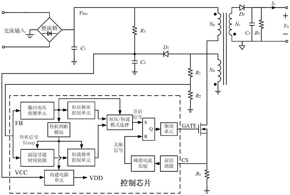
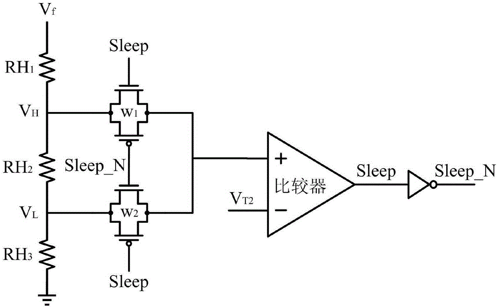
[0040] like figure 2 As shown, the present invention provides a control chip that realizes the low standby power consumption of AC-DC switching power supply. Based on the existing AC-DC primary side control converter topology, a standby judgment module is added to the control chip so that the control chip can Low power consumption is achieved in standby mode. The control chip includes output voltage detection unit, constant voltage frequency control unit, standby judgment module, secondary on-time detection unit, constant current frequency control unit, constant voltage / constant current mode selection unit, leading edge blanking unit, peak current Comparison unit, RS flip-flop, drive unit and built-in power supply unit.

[0041] The operating principle...


PUM


Abstract

The invention discloses a control chip for realizing low-standby power consumption of an AC-DC switch power supply. The control chip includes an output voltage detecting unit, a constant voltage frequency control unit, a standby determination module, a secondary conduction time detecting unit, a constant current frequency control unit, a constant voltage / constant current mode selection unit, a leading edge blanking unit, a peak value current comparison unit, an RS trigger, a driving unit, and a built-in power supply unit. From the aspect of the circuit structure of the switch power supply control chip, the internal circuit structure of the chip can be adjusted under the system standby state, standby signals of the system are generated by the standby determination module and part of unnecessary circuit modules are turned off when the normal standby of the system is maintained, and the work current for chip standby is reduced. Meanwhile, the inner power supply voltage of the chip is reduced under the system standby state, and the standby power consumption of the control chip can be further reduced under the condition that the dynamic performance is not influenced.

Description

technical field [0001] The invention belongs to the technical field of switching power supply control, and in particular relates to a control chip for realizing low standby power consumption of an AC-DC switching power supply. Background technique [0002] With the global energy shortage, people put forward higher and higher requirements for the energy saving of daily equipment. Among them, the mass popularization of consumer electronic devices in recent years has brought convenience and pleasure to people, and at the same time, it has also become a huge energy consumption group. For charging equipment corresponding to electronic equipment, not only high conversion efficiency is required, but also low standby power consumption is required. As an authoritative certification standard, Energy Star has been upgraded from a one-star certification standard to a five-star certification standard, and the requirements for the standby power consumption of AC-DC switching power suppli...

Claims


Application Information

Patent Timeline
IPC IPC(8): H02M7/217
CPCH02M7/217H02M1/0032Y02B70/10
Inventor 刘侃奚剑雄孙可旭何乐年朱勤为励晔黄飞明
Owner ZHEJIANG UNIV
Learn More