Method and device for separating oil-bearing metal powder

A technology of metal powder and centrifugal separation, which is applied in the direction of solid separation, wet separation, chemical instruments and methods, etc., can solve the problems of low metal recovery rate and environmental pollution, and achieve high degree of automation, easy operation of equipment and good stability Effect

Active Publication Date: 2016-03-23
大连远东新材料科技有限公司
View PDF7 Cites 7 Cited by
  • Summary
  • Abstract
  • Description
  • Claims
  • Application Information

AI Technical Summary

Problems solved by technology

This method releases a large amount of flue gas to pollute the environment, and the metal recovery rate is low due to the oxidation of high-temperature metal powder

Method used


Image

  • Method and device for separating oil-bearing metal powder
  • Method and device for separating oil-bearing metal powder
  • Method and device for separating oil-bearing metal powder

Examples


Embodiment 1

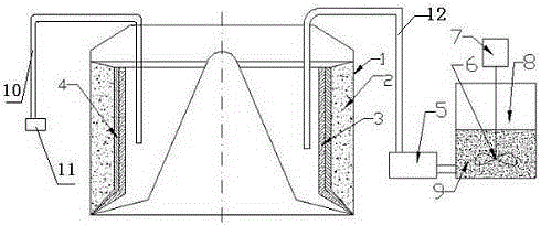
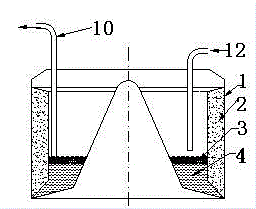
[0020] A method for separating oil-containing metal powder, adding water to the oil-containing metal powder, centrifuging the oil-containing metal powder added with water, under the action of centrifugal force, the water squeezes out the oil, and the water occupies the position of the oil to replace the oil, A water-containing metal powder layer, a water layer and an oil layer are formed. The oil-containing metal powder is an oil-containing ground metal powder. The oil-containing metal powder is pretreated, and oil is added to the oil-containing metal powder to make an oil slurry 9, and the slurry is centrifuged to separate a part of the oil. The oil added to the oil-containing metal powder is the same oil as the oil-containing metal powder itself.

[0021] A device for separating oily metal powder, comprising a centrifuge, a feed pipe 12, a slurry pump 5, a stirring paddle 6, a slurry tank 8 and a speed regulating motor 7, one end of the feed pipe 12 extends into the centrif...

Embodiment 2

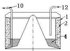
[0024] A method for separating oil-containing metal powder, adding water to the oil-containing metal powder to make a slurry, centrifuging the oil-containing metal powder added with water, under the action of centrifugal force, the water squeezes out the oil, and the water occupies the position of the oil. The oil is displaced out to form a water-containing metal powder layer, a water layer and an oil layer. Oil-containing metal powder is a metal powder containing grinding.

[0025] A device for separating oily metal powder, comprising a centrifuge, a feed pipe 12, a slurry pump 5, a stirring paddle 6, a slurry tank 8 and a speed regulating motor 7, one end of the feed pipe 12 extends into the centrifuge, and The other end of the material pipe 12 is connected with the slurry pump 5, the slurry pump 5 is connected with the slurry mixing tank 8, the stirring paddle 6 is located in the slurry mixing tank 8, and the speed regulating motor 7 is connected at the top of the stirring ...


PUM


Abstract

The invention relates to a method and device for separating oil-bearing metal powder. Water is added to the oil-bearing metal powder, and the oil-bearing metal powder with the water is separated centrifugally; under the action of centrifugal force, oil is extruded through the water, the position of the oil is occupied by the water, and the oil is replaced by the water, so that a water-bearing metal powder layer, a water layer and an oil layer are formed. The device for separating the oil-bearing metal powder comprises a centrifugal machine, a feeding pipe, a slurry pump, a stirring paddle, a slurry mixing tank and an adjustable-speed motor. One end of the feeding pipe stretches into the centrifugal machine, and the other end of the feeding pipe is connected with the slurry pump. The slurry pump is connected with the slurry mixing tank, and the stirring paddle is located in the slurry mixing tank. The adjustable-speed motor is connected to the upper end of the stirring paddle. The water is used as a replacement medium, the oil can be recycled and is protected against qualitative change, the water for replacement can be used repeatedly, and therefore the situation that water is drained and affects the environment is avoided. The device is easy and convenient to operate, the working strength is low, the automation degree is high, and the oil content of processed metal powder oil-bearing materials is smaller than 1.2%.

Description

technical field [0001] The invention belongs to the field of separating oil-containing metal powder, and in particular relates to a method and device for separating oil-containing metal powder. Background technique [0002] Metal powder often contains oil, and grinding metal powder is one of them. Grinding metal powder contains grinding oil, generally with an oil content of about 15%. Grinding metal powder is a by-product of grinding metal workpieces with grinding wheels. If it is not treated, it will become waste and be discarded, which will pollute the environment. The metal powder produced during grinding has a relatively high real density, and the metal powder will settle down quickly and become solid, which is not conducive to automatic conveying. [0003] There are three existing methods for separating metal powder and oil: [0004] The first method is to manually feed the centrifuge. The oil passes through the filter bag gap and the small hole on the drum wall and i...

Claims


Application Information

Patent Timeline
Patent Type & Authority Applications(China)
IPC IPC(8): B03B5/32B04B11/04B04B1/00
CPCB03B5/32B04B1/00B04B11/04
Inventor 齐树民刘海强
Owner 大连远东新材料科技有限公司
Why Eureka
Try Eureka