A welding torch housing and a welding torch having the same

A shell and welding torch technology, which is applied in the field of welding torch shells and welding torches, can solve the problems of complicated handle manufacturing process, inapplicability to mass production, inconvenient use, etc., and achieve the effect of simple welding torch, practical functions and convenient installation

Active Publication Date: 2018-01-30
SHANGHAI HUGONG ELECTRIC WELDING MACHINE MFG
View PDF9 Cites 0 Cited by
  • Summary
  • Abstract
  • Description
  • Claims
  • Application Information

AI Technical Summary

Problems solved by technology

[0002] The welding torch in the original MIG product is bulky, has many consumables, and the handle is complicated to make, which is inconvenient to use. It is not suitable for mass production and small economical MIG (inert gas shielded welding) products for household use.

Method used


Image

  • A welding torch housing and a welding torch having the same
  • A welding torch housing and a welding torch having the same
  • A welding torch housing and a welding torch having the same

Examples


Embodiment Construction

[0031] The advantages of the present invention will be further elaborated below in conjunction with the accompanying drawings and specific embodiments.

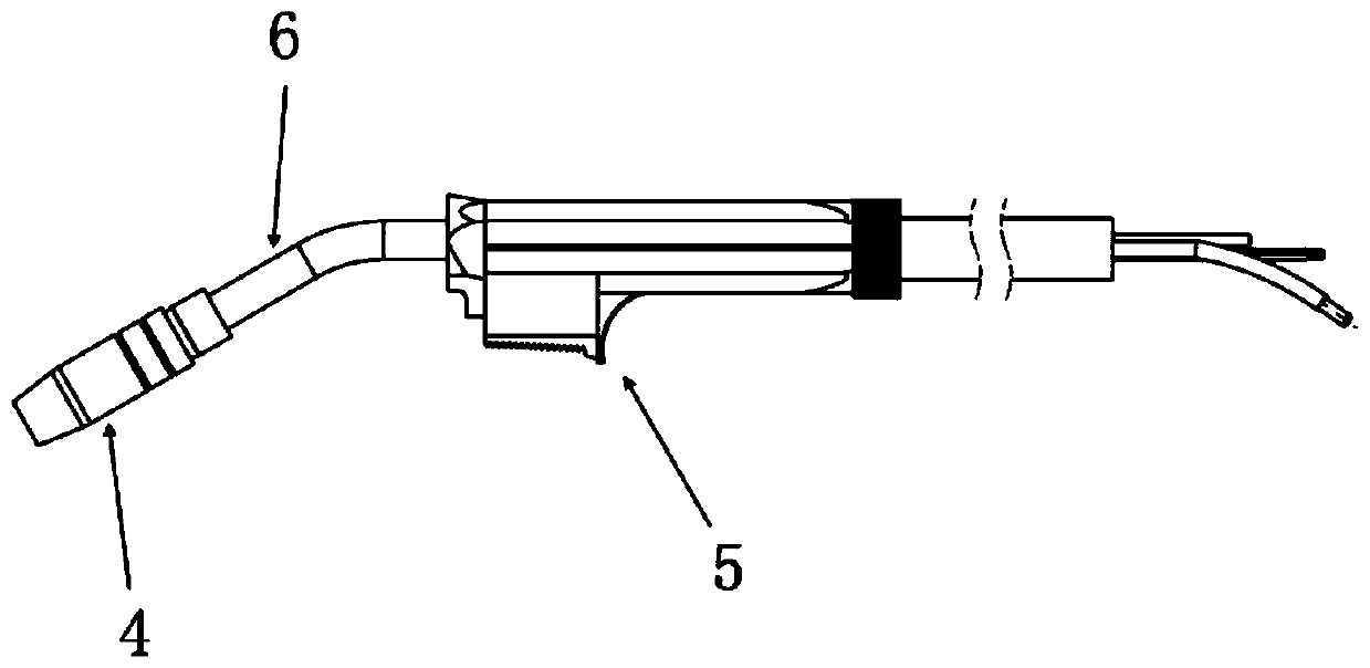
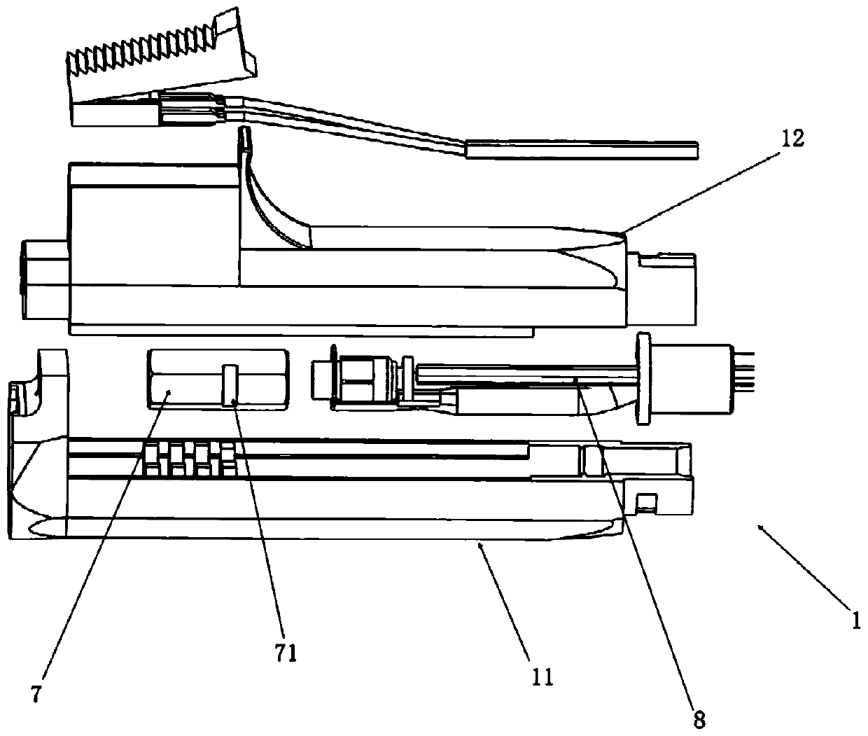
[0032] Such as Figure 1 to Figure 8 As shown, the present invention discloses a welding torch housing 1 , which is a hollow cavity formed by detachably connecting an upper housing 11 and a lower housing 12 .

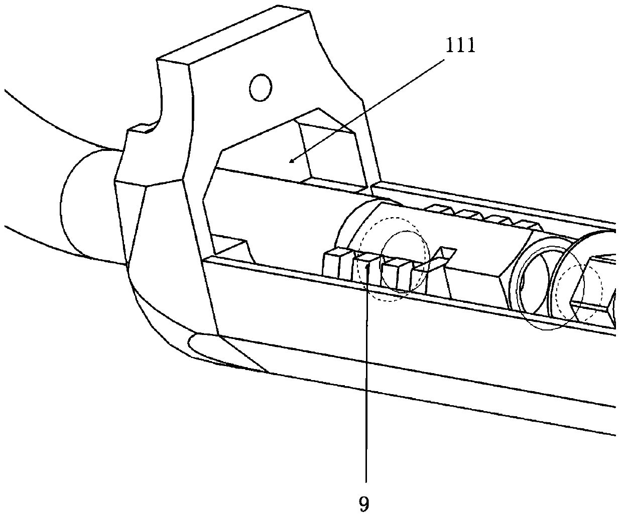
[0033] Such as image 3 and Figure 4 As shown, the front end of the upper housing 11 is provided with an outlet 111 , and the front end of the lower housing 12 is provided with an extension 121 corresponding to the outlet 111 , and the extension 121 of the lower housing 12 is inserted into the outlet 111 . Further, the outlet portion 111 is a trapezoidal hole, and the extension portion 121 is a trapezoidal extension part.

[0034] Such as Figure 5 As shown, concave locking slots 2 are respectively provided on the outer surfaces of the rear ends of the upper shell 11 and the lower shell 12 .

[0035] Such as Fi...


PUM


Abstract

The invention provides a welding gun shell. The welding gun shell is a hollow cavity formed by detachably connecting an upper shell with a lower shell. An outlet portion is formed in the front end of the upper shell. The front end of the lower shell is provided with an extending portion corresponding to the outlet portion. The extending portion of the lower shell is inserted into the outlet portion. Concave locking clamping grooves are formed in the outer surfaces of the rear ends of the upper shell and the lower shell respectively. The welding gun shell is further provided with ring locking sleeves corresponding to the concave locking clamping grooves. The inner walls of the ring locking sleeves are symmetrically provided with bosses. The ring locking sleeves are pushed into the outer surfaces of the rear ends of the upper shell and the lower shell and arranged on the outer surfaces in a sleeving manner after the bosses of the ring locking sleeves are aligned with the concave locking clamping grooves so as to be rotated and fastened so that the welding gun shell can be assembled. The invention further provides a welding gun with the welding gun shell.

Description

technical field [0001] The invention relates to a welding gun housing and a welding gun with the housing. Background technique [0002] In the original MIG products, the welding torch has a large volume, many consumables, complicated handle manufacturing process, and inconvenient use. It is not suitable for mass production and small economical MIG (inert gas shielded welding) products for household use. Contents of the invention [0003] In order to overcome the above-mentioned technical defects, the object of the present invention is to provide a simple, portable, functional and practical welding torch housing and welding torch suitable for mass production. [0004] The invention discloses a welding torch shell, the shell is a hollow cavity formed by detachable connection of an upper shell and a lower shell; The front end is provided with a protruding part corresponding to the outlet part, and the protruding part of the lower housing is inserted into the outlet part; the...

Claims


Application Information

Patent Timeline
Patent Type & Authority Patents(China)
IPC IPC(8): B23K9/173B23K9/28B23K9/26B23K9/32
CPCB23K9/173B23K9/26B23K9/28B23K9/32
Inventor 不公告发明人
Owner SHANGHAI HUGONG ELECTRIC WELDING MACHINE MFG
Why Eureka
Try Eureka