
Multifunctional plate bending machine with plate shearing mechanism

A plate bending machine, multi-functional technology, applied in the direction of metal rolling mill stands, manufacturing tools, metal rolling racks, etc., can solve the problems of single function, large volume, high price, etc., and achieve the effect of reducing the occupied space

Inactive Publication Date: 2016-03-23
CHUZHOU PINZHIDA ELECTRIC TECH
View PDF6 Cites 1 Cited by
  • Summary
  • Abstract
  • Description
  • Claims
  • Application Information

AI Technical Summary

Problems solved by technology

[0002] At present, the plate bending machines on the market need to meet the processing requirements of different sizes of sheet metal, resulting in relatively large volume, heavy weight, high price, and relatively simple functions.

Method used


Image

  • Multifunctional plate bending machine with plate shearing mechanism
  • Multifunctional plate bending machine with plate shearing mechanism
  • Multifunctional plate bending machine with plate shearing mechanism

Examples


Embodiment 1

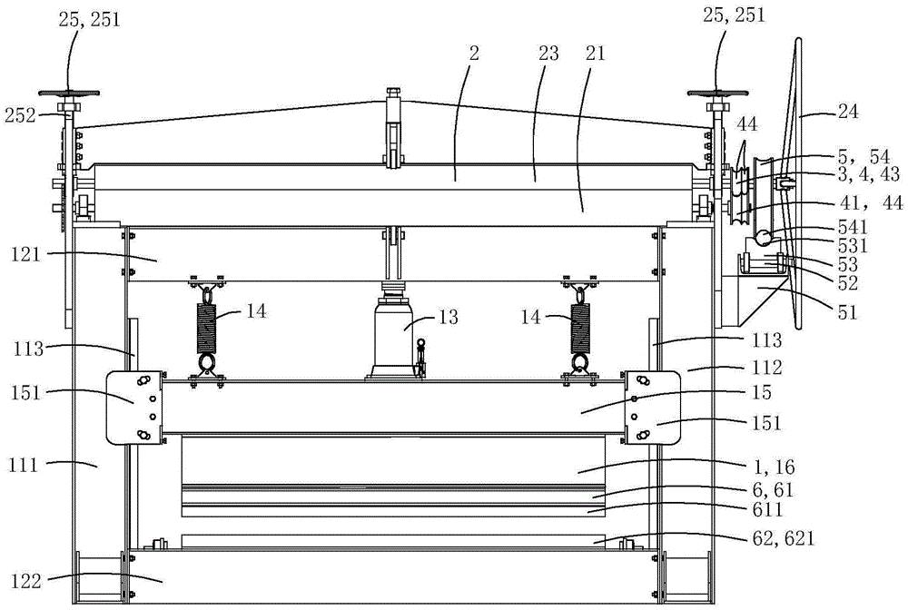
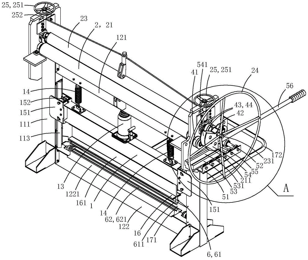
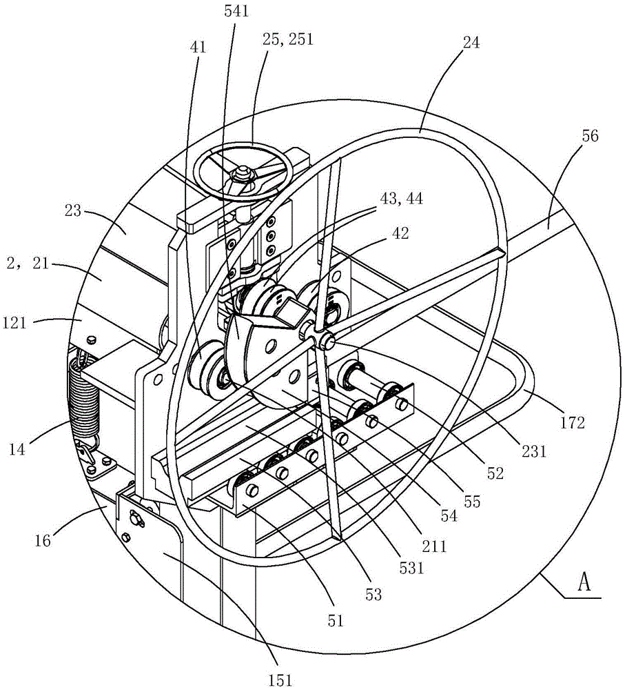
[0012] Figure 1 to Figure 5 A specific embodiment of the present invention is shown, in which, figure 1 Is a schematic diagram of the first structure of the present invention; figure 2 Yes figure 1 A schematic diagram of a three-dimensional structure of the plate bending machine shown; image 3 Yes figure 2 The partial enlarged schematic diagram of A in the plate bending machine shown; Figure 4 Yes figure 1 A schematic diagram of a three-dimensional structure of the plate bending machine shown from another angle; Figure 5 Yes Figure 4 The partial enlarged schematic diagram of B in the plate bending machine shown.

[0013] This embodiment is a multifunctional plate bending machine, see Figure 1 to Figure 5 As shown, it includes a plate bending mechanism 1, a plate rolling mechanism 2 and a pipe bending mechanism 3. The bending mechanism includes a left pillar 111, a right pillar 112, a first horizontal fixed beam 121, a second horizontal fixed beam 122, a cylinder 13, and a ...


PUM


Abstract

The invention discloses a multifunctional plate bending machine with a plate shearing mechanism. The multifunctional plate bending machine with the plate shearing mechanism comprises a plate bending mechanism and the plate shearing mechanism. The plate bending mechanism comprises a left supporting pillar, a right supporting pillar, a first horizontal fixed beam and a second horizontal fixed beam. The plate shearing mechanism comprises a cross shearing cutter and a auxiliary shearing cutter, wherein the cross shearing cutter is rotationally arranged on an I-shaped beam and can rotates around a rotary shaft of the cross shearing cutter to abut against the bottom wall of the I-shaped beam; the auxiliary shearing cutter is rotationally arranged on the second horizontal fixed beam or rotationally arranged on the left supporting pillar and the right supporting pillar and can rotate around a rotary shaft of the auxiliary shearing cutter to abut against the second horizontal fixed beam. The position is a shearing position, and at the time a V-shaped blade groove opening of the auxiliary shearing cutter is upward. The auxiliary shearing cutter further rotates to the front side of the second horizontal fixed beam, and the position is a storage position. The multifunctional plate bending machine with the plate shearing mechanism achieves multiple functions in one machine.

Description

Technical field [0001] The invention belongs to the technical field of mechanical processing, and specifically relates to a multifunctional plate bending machine with a plate shearing mechanism. Background technique [0002] At present, the plate bending machines on the market need to meet the processing requirements of different sizes of sheet materials, resulting in a relatively large volume, a heavier weight, a higher price, and a single function. Summary of the invention [0003] The purpose of the present invention is to provide a multifunctional plate bending machine with a shearing mechanism. [0004] The technical solution to achieve the objective of the present invention is: a multifunctional plate bending machine with a plate shearing mechanism, including a plate bending mechanism and a plate shearing mechanism; the plate bending mechanism includes a left pillar, a right pillar, a first horizontal fixed beam, and a second horizontal Fixed beams, cylinders, horizontal rail...

Claims


Application Information

Patent Timeline
IPC IPC(8): B23P23/04B21D1/00B21D7/08B21B1/22B21B31/16
CPCB23P23/04B21B1/22B21B31/16B21D1/00B21D7/08
Inventor 刘开成
Owner CHUZHOU PINZHIDA ELECTRIC TECH
Learn More