Rivet pressing machine for end cover

A technology for riveting presses and end caps, applied to presses, stamping machines, manufacturing tools, etc., can solve problems such as high bearing noise, potential safety hazards, undervoltage, etc., reduce the incidence of bearing noise, improve safe use, The effect of avoiding safety hazards

Inactive Publication Date: 2016-03-23
GREE ELECTRIC APPLIANCES INC +1
View PDF11 Cites 9 Cited by
  • Summary
  • Abstract
  • Description
  • Claims
  • Application Information

AI Technical Summary

Problems solved by technology

[0003] But above-mentioned oil press and air press have oil pressure, air pressure in the process of pressing end cover and cause unstable product quality, and the cylinder body of air press and oil press is easy to come off and fly out, causes certain potential safety hazard; Meanwhile, in manual During the mold adjustment process, the pressing origin is not easy to control, and phenomena such as undervoltage, overvoltage or poor concentricity occur, resulting in the problem of high bearing noise
[0004] In view of the above problems, we need an end cap riveting machine to solve the problem of unstable product quality due to poor oil pressure and air pressure in the existing end cap riveting press, and the cylinder body of the air press and hydraulic machine is easy to fall off and fly out. It causes certain safety hazards, and it is not easy to control the pressing origin during the manual mold adjustment process, resulting in undervoltage, overvoltage or poor concentricity, which leads to the problem of high bearing noise

Method used


Image

  • Rivet pressing machine for end cover
  • Rivet pressing machine for end cover
  • Rivet pressing machine for end cover

Examples


Embodiment Construction

[0027] The technical solutions of the present invention will be further described below in conjunction with the accompanying drawings and through specific implementation methods.

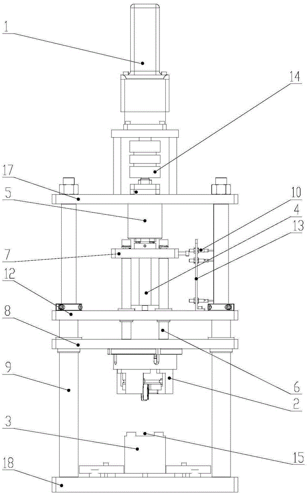
[0028] figure 1 It is a schematic structural view of the end cap riveting machine provided by the specific embodiment of the present invention. Such as figure 1 As shown, this embodiment proposes an end cap riveting press, which includes a servo motor 1, a lifting mechanism, an upper mold 2 and a lower mold 3, and the servo motor 1 drives the upper mold 2 to lift by driving the lifting mechanism. During the descent, the end cap placed on the lower die 3 is riveted. Wherein, the servo motor 1 is installed on the servo motor fixing plate 17, the lower mold 3 is installed on the bottom plate 18, and the lower mold 3 is provided with a positioning groove 15 for the positioning of the end cap.

[0029] In this embodiment, the lifting mechanism is preferably a ball screw mechanism. The ball screw mecha...


PUM


Abstract

The invention relates to the field of servo motor assembling and machining equipment, in particular to a rivet pressing machine for an end cover. The rivet pressing machine comprises a servo motor, a lifting mechanism, an upper mold and a lower mold. The servo motor drives the upper mold to rise and fall by driving the lifting mechanism. In the falling process of the upper mold, the end cover placed on the lower mold is subjected to rivet pressing. According to the rivet pressing machine for the end cover, compared with the prior art, the servo motor drives the upper mold to rise and fall by driving the lifting mechanism; in the falling process of the upper mold, the end cover placed on the lower mold is subjected to rivet pressing, and the end cover and a stator are automatically connected in a pressed mode; precise control is achieved by adjusting a mold manually, and the product quality is improved; moreover, the noise occurrence rate of bearings is reduced, and operating of the mechanism is stable; the potential safety hazards due to the fact that a cylinder body of an existing air cylinder type rivet pressing machine for the end cover or an existing oil cylinder type rivet pressing machine for the end cover falls off and flies off are effectively avoided, and the safe usability is improved.

Description

technical field [0001] The invention relates to the field of motor assembly and processing equipment, in particular to an end cover riveting press. Background technique [0002] At present, in the crimping operation of the stator end cover of the motor, an oil press or an air press is generally used for the end cover crimping. Among them, the hydraulic press is a kind of hydraulic press that circulates the hydraulic oil in the oil tank through the check valve to make the oil cylinder / piston circulate and do work, so as to complete certain mechanical actions as a productive force. The hydraulic press uses special hydraulic oil as the working medium and the hydraulic pump as the power source. The force of the pump makes the hydraulic oil enter the cylinder / piston through the hydraulic pipeline. Under the action of high-pressure oil, the cylinder moves to complete the pressing process. device of. Pneumatic press is also called pneumatic stamping machine. It uses the high-pres...

Claims


Application Information

Patent Timeline
Patent Type & Authority Applications(China)
IPC IPC(8): B30B1/18B30B15/14B21D39/00
CPCB30B1/181B21D39/00B30B15/14
Inventor 安强龙唐世勇
Owner GREE ELECTRIC APPLIANCES INC
Why Eureka
Try Eureka