Electromagnetic directional valve

A technology of electromagnetic reversing valve and electromagnet, which is applied in valve details, multi-way valves, valve devices, etc., can solve problems such as short service life, hidden safety accidents, and slipping downhill, so as to achieve long service life and improve use reliability effect

Active Publication Date: 2016-03-23
CHANGZHOU KANGSHIDA ELECTROMECHANICAL CO LTD
View PDF5 Cites 11 Cited by
  • Summary
  • Abstract
  • Description
  • Claims
  • Application Information

AI Technical Summary

Problems solved by technology

[0003] The electromagnetic reversing valve used by existing engineering vehicles includes a valve body, a valve core and an electromagnet assembly. Assembled with the electromagnet assembly and communicated with the inner cavity of the electromagnet assembly, the valve body includes three oil passages and an oil return passage, and the three oil passages are connected to the first oil port, the second oil port and the oil inlet respectively. The oil return port is connected with the oil return passage, and the three oil passages and the oil return passage are connected with the main hole of the valve body. The existing oil return passage is not only used as an oil return passage for pressure oil circulation, but also as a The oil pressure balance channel at both ends of the spool, when the pressure oil returns to the oil through the oil return channel, it is easy to cause the pollutants contained in the pressure oil to enter the inner cavity of the electromagnet assembly, and the pollutants are absorbed by the armature. It will gradually consume the electromagnetic force of the electromagnet assembly, and the pollutants accumulated over a long period of time will easily block the inner cavity of the electromagnet assembly, making the electromagnet assembly invalid; Unable to control and shift gears normally makes it difficult for the engineering vehicle to climb uphill and slide downhill. If it is driven in a high gear on flat ground, it is easy to fail to brake the vehicle, which may cause major safety accidents
The electromagnetic reversing valve in the prior art also has the disadvantages of short service life, weak anti-pollution ability, poor reliability, etc.

Method used


Image

  • Electromagnetic directional valve
  • Electromagnetic directional valve
  • Electromagnetic directional valve

Examples


Embodiment Construction

[0039] The present invention will be further described below in conjunction with the accompanying drawings and given embodiments, but is not limited thereto.

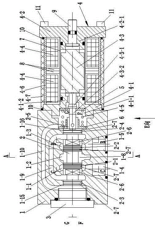
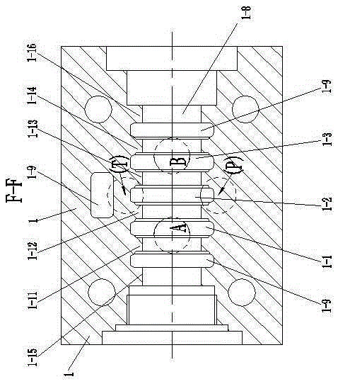
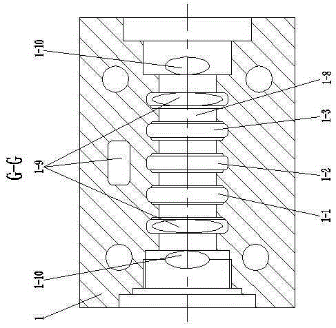
[0040] Such as figure 1 , 2 , 3, 4, 5, 6, 7, 8, 9, 10, 11, and 12, an electromagnetic reversing valve includes a valve body 1, a valve core 2, a valve body end cover 3 and an electromagnet assembly 4;

[0041] The valve body 1 includes a first oil port 1-4, a second oil port 1-5, an oil return port 1-6, an oil inlet port 1-7 and a valve body main hole 1-8 arranged along its axial direction , and the first oil passage 1-1, the second oil passage 1-2 and the third oil passage 1-3 arranged axially along the inner wall of the main hole 1-8 of the valve body, the first oil passage 1-4 It communicates with the first oil passage 1-1, the second oil port 1-5 communicates with the third oil passage 1-3, the oil inlet 1-7 communicates with the second oil passage 1-2, and the first The oil passage 1-1, the second oil passage 1-...


PUM


Abstract

The invention relates to an electromagnetic directional valve which comprises a valve body, a valve element, a valve body end cover and an electromagnet assembly. The valve body comprises a valve body main hole. A spring seat is arranged at one end of the valve element in a sleeving manner. A third valve element boss and a fourth valve element boss are arranged at the two ends of the valve element respectively. An oil pressure balance runner is arranged in the valve body, the two ends of the oil pressure balance runner are located on the outer sides of the two ends of an oil return runner respectively, and the two ends of the oil pressure balance runner are communicated with the valve body main hole. A fifth valve body step and a sixth valve body step are arranged at the two ends of the valve body main hole in the valve body in the axial direction respectively, and located on the outer sides of the two ends of the oil return runner respectively and on the inner sides of the two ends of the oil pressure balance runner respectively. The third valve element boss and the fourth valve element boss at the two ends of the valve element are in sliding fit with the corresponding fifth valve body step and sixth valve body step respectively. The other side of the spring seat can abut against the sixth valve body step and/or the fourth valve element boss. Pollutants can be prevented from entering the electromagnet assembly, use reliability is improved, and the service life is long.

Description

technical field [0001] The invention relates to an electromagnetic reversing valve, in particular to an electromagnetic reversing valve for engineering vehicles. Background technique [0002] The engineering vehicles described in the present invention include forklifts, tractors, loaders and the like. [0003] The electromagnetic reversing valve used by existing engineering vehicles includes a valve body, a valve core and an electromagnet assembly. Assembled with the electromagnet assembly and communicated with the inner cavity of the electromagnet assembly, the valve body includes three oil passages and an oil return passage, and the three oil passages are connected to the first oil port, the second oil port and the oil inlet respectively. The oil return port is connected with the oil return passage, and the three oil passages and the oil return passage are connected with the main hole of the valve body. The existing oil return passage is not only used as an oil return pas...

Claims


Application Information

Patent Timeline
Patent Type & Authority Applications(China)
IPC IPC(8): F16K11/07F16K27/04F16K31/11
CPCF16K11/07F16K27/04F16K27/041F16K31/061F16K31/0675F16K31/10F16K31/60
Inventor 王小康岳烨冬盛建新
Owner CHANGZHOU KANGSHIDA ELECTROMECHANICAL CO LTD
Why Eureka
Try Eureka