Computer assisted full-waveband spectrometer wavelength calibration method

A computer-aided calibration method technology, applied in spectrometry/spectrophotometry/monochromator, radiation pyrometry, instruments, etc., can solve complex spectral line profiles, limited accuracy of wavelength calibration results, and limited number of light sources And other issues

Inactive Publication Date: 2016-03-23
TSINGHUA UNIV
View PDF5 Cites 20 Cited by
  • Summary
  • Abstract
  • Description
  • Claims
  • Application Information

AI Technical Summary

Problems solved by technology

[0005] Question 1: Since the wavelength calibration result is obtained by fitting the "peak wavelength-pixel position" data, the spectral line data depends on the selected calibration spectral line. In order to fit the data and improve the accuracy of the calibration result, in When selecting calibration lines, a sufficient number of lines must be ensured
Due to the limited number of standard light sources currently used for wavelength calibration, it is difficult to select a suitable standard light source for wavelength calibration for some spectrometers with narrow operating bands.
[0006] Question 2: In the calibration experiment, each set of data read from the detector is a spectral line data map containing the entire working band
[0010] The errors of the calculation method and the approximate formula mainly appear in two stages: first, when determining the pixel position of the peak of the spectral line, as mentioned above, the spectral line data output by the spectrometer is affected, and the spectral line profile becomes very complicated. When using Ford function, Gaussian function, Lorenz function or polynomial function will cause some errors when it is fitted and reconstructed; second, use polynomial function to fit the "peak wavelength-pixel position" data to get the distance between wavelength and pixel position A certain error will also be brought about when the relation function of
[0011] Due to the existence of the above problems, the accuracy of the wavelength calibration results will be limited

Method used


Image

  • Computer assisted full-waveband spectrometer wavelength calibration method
  • Computer assisted full-waveband spectrometer wavelength calibration method
  • Computer assisted full-waveband spectrometer wavelength calibration method

Examples


Embodiment Construction

[0045] The content of the present invention mainly analyzes the three problems of the selection of the calibration spectral line, the acquisition of the spectral line data and the processing of the data and adopts corresponding methods to solve or improve it, specifically as follows:

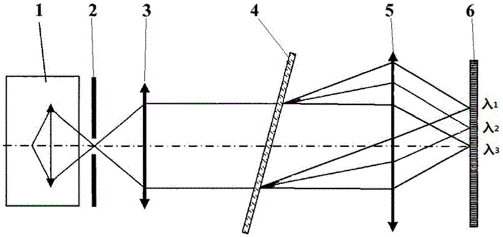
[0046] First, the selection of the calibration spectral line, the standard light source with different characteristic spectral lines is combined by the optical path coupling method to obtain the combined light source. The output signal of such a combined light source will have all the characteristic lines of the selected light source. By combining light sources, the number of characteristic spectral lines used for wavelength calibration can be increased to meet the conditions of the wavelength calibration process. Combining a suitable standard light source can calibrate the spectrometer in any working band.

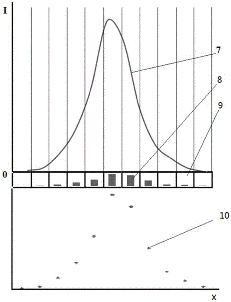
[0047] Second, the acquisition of spectral line data, as mentioned above, regarding th...


PUM


Abstract

The invention provides a computer assisted full-waveband spectrometer wavelength calibration method, relates to wavelength calibration methods for spectrometers with array type detectors, and belongs to the technical field of computer assisted spectrometer wavelength calibration. The method is characterized by successively comprising the following steps (1) a spectrometer wavelength calibration system including a combined light source and computer program is established; (2) the spectral line wavelength of the combined light source, basic parameters of the spectrometer and the calibration condition are input to a computer; (3) data of all calibrated spectral lines is obtained successively; (4) spectral line contour reconstruction and peak value determination are carried out on the spectral line data in different manners; (5) a peak value wavelength and pixel position data is fit in a three-order polynomial manner, and a calibration result is obtained; (6) the result is verified; and (7) the error degrees of different peak searching methods are compared, and the result of the highest precision is selected as the final result. The calibration process is made automatic, the problems in present spectrometer wavelength calibration are solved, and the precision of the wavelength calibration result is improved.

Description

technical field [0001] The invention relates to a wavelength calibrating method for an array detector spectrometer working in an optical band, and belongs to the technical field of spectroscopic instrument wavelength calibrating. Background technique [0002] figure 1 It is a schematic diagram of the basic structure of a spectrometer using an array detector. The light emitted by the light source 1 is collimated through the incident slit or hole 2 and the collimating mirror 3, and irradiated on the grating 4. After the grating is dispersed, the beams of different wavelengths are converged on different positions on the detector 6 by the imaging mirror 5 to form spectral images. The detector pixels acquire the light intensity of the spectral image and convert it into an electrical signal output, which is the spectral line data of the spectral image. figure 2 Shown is a schematic diagram of integral sampling of a characteristic spectral line on the detector, the spectral line...

Claims


Application Information

Patent Timeline
Patent Type & Authority Applications(China)
IPC IPC(8): G01J3/28G01J3/10
CPCG01J3/10G01J3/28G01J3/2823G01J2003/106
Inventor 杨怀栋黎武南孙利群金国藩
Owner TSINGHUA UNIV
Why Eureka
Try Eureka