
An automatic detection system for metal strain gauge defects

An automatic detection and strain gauge technology, applied in the direction of optical testing flaws/defects, etc., can solve the problems of inconsistent judgment standards, high labor intensity, low detection efficiency, etc., to reduce labor intensity, avoid missed inspections, improve The effect of efficiency

Inactive Publication Date: 2018-07-13
NANJING BIO INSPIRED INTELLIGENT TECH
View PDF7 Cites 0 Cited by
  • Summary
  • Abstract
  • Description
  • Claims
  • Application Information

AI Technical Summary

Problems solved by technology

[0006] One of the purposes of the present invention is to address the above deficiencies, to provide an automatic detection system for metal strain gauge defects, in order to solve the problems of manual visual inspection of the quality of strain gauges in the prior art that cannot be unified, easy to miss inspection, and labor-intensive Large, low detection efficiency and other technical problems

Method used


Image

  • An automatic detection system for metal strain gauge defects
  • An automatic detection system for metal strain gauge defects

Examples


Embodiment Construction

[0019] The present invention will be further elaborated below in conjunction with the accompanying drawings.

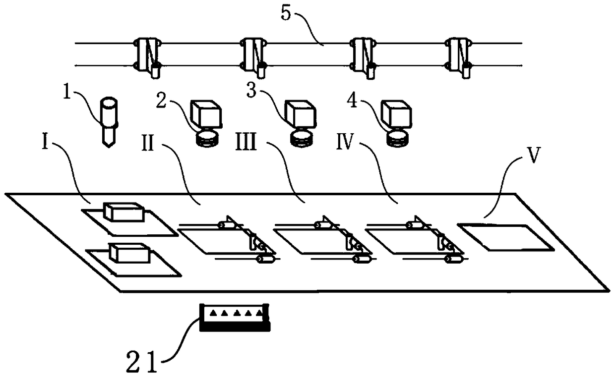
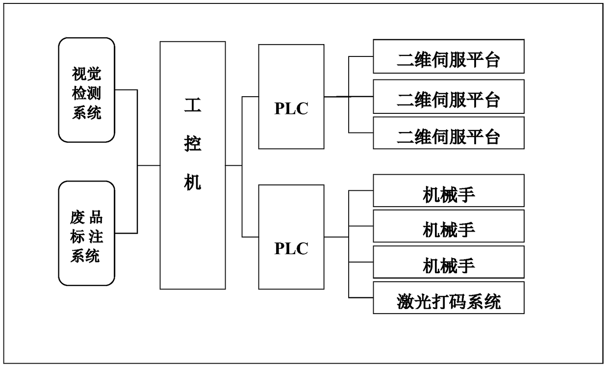
[0020] refer to figure 1 As shown, one embodiment of the present invention is an automatic detection system for metal strain gauge defects, the system includes a feeding leveling mechanism 1, a visual inspection mechanism 2, a laser marking mechanism 3, a waste labeling mechanism 4 and a manipulator assembly 5, the aforementioned The feeding leveling mechanism 1, visual inspection mechanism 2, laser coding mechanism 3 and waste labeling mechanism 4 are respectively installed on the loading station I, visual inspection station II, coding station III and waste labeling below the manipulator assembly 5. Station IV; and the above-mentioned visual inspection mechanism 2, laser marking mechanism 3 and waste product marking mechanism 4 all need to be connected to the control system;

[0021] More specifically, the feeding leveling mechanism 1 includes a station platform on ...


PUM


Abstract

The invention discloses an automatic detection system for metal strain gauge defects, which belongs to a strain gauge detection device. The system includes a feeding leveling mechanism, a visual detection mechanism, a laser marking mechanism, a waste product marking mechanism and a manipulator assembly. The feeding leveling mechanism, visual inspection mechanism, laser coding mechanism and waste product marking mechanism are respectively installed on the feeding station, visual inspection station, coding station and waste product labeling station under the manipulator assembly; the visual inspection mechanism, laser Both the coding mechanism and the waste labeling mechanism are connected to the control system; multiple stations in the system perform operations such as loading, visual inspection, laser coding, and waste labeling on the strain gauge in sequence. The visual inspection mechanism uses a unified image recognition standard to identify The strain gauges on the workstations are tested, and the waste product marking system sprays marks on the unqualified strain gauges, which effectively avoids the occurrence of missed inspections, improves the efficiency of strain gauge detection, and reduces the labor intensity.

Description

technical field [0001] The invention relates to a strain gauge detection device, more specifically, the invention mainly relates to a metal strain gauge defect automatic detection system. Background technique [0002] Resistance strain gage (Resistance strain gage) is a kind of transducer (also known as resistance strain gage), which can convert the strain on engineering components, that is, dimensional change into resistance change, and is referred to as strain gage for short. Generally, it is composed of sensitive grid, lead wire, adhesive, substrate and cover layer. The finished strain gauge is a sandwich structure, which is composed of base material, metal foil and cladding material; the specifications and shapes of the strain gauge products are different, and the grids are arranged horizontally, vertically, 45 degrees obliquely and circularly, etc. There are uniaxial, Divided into biaxial and triaxial, the internal structure of the strain gauge is very small. Generally...

Claims


Application Information

Patent Timeline
Patent Type & Authority Patents(China)
IPC IPC(8): G01N21/89
Inventor 姚举禄戴振东吉爱红黄肖飞
Owner NANJING BIO INSPIRED INTELLIGENT TECH
Learn More