Monitoring method for electrical endurance of arc-extinguishing chamber of circuit breaker and determination method for initial time of arcing current

A starting time and circuit breaker technology, which is applied in the field of judging the starting time of arcing current and monitoring the electric life of circuit breaker arc extinguishing chamber, can solve the problem of inability to accurately judge the arcing time of fault breaking current and the inability to effectively and accurately determine arcing Start time, difficulty in determining which field probe signal is desired, etc.

Inactive Publication Date: 2016-03-23
CHINA XIDIAN GRP CO LTD
View PDF4 Cites 33 Cited by
  • Summary
  • Abstract
  • Description
  • Claims
  • Application Information

AI Technical Summary

Problems solved by technology

[0003] The arcing time of the circuit breaker has a great influence on the result of the electrical life. Generally, the arcing time can be determined by the zero-crossing point of the breaking current. The key problem is that this method cannot accurately obtain the arcing time of the contacts of each phase. It can only be determined according to the characteristics of the instantaneous change of the breaking current, and the randomness is large
In the prior art, there are still the following processing methods: ①Using the auxiliary node signal of contact opening and closing, combined with the breaking current to determine, but due to the action delay of the auxiliary node and the large dispersion of the action time of the auxiliary contact, it cannot be effectively and accurately determined Arcing start time
②Use the magnetic field signal to determine the start time of arcing, but it ignores the asynchrony of the three phases
When multiple high-voltage circuit breakers are operated at the same time or successively, the magnetic field signals overlap, and it is difficult to determine which magnetic field probe receives the required signal; high-frequency electromagnetic radiation will also be generated when the high-voltage circuit breaker is closed, and the trigger circuit may be activated. Misaccumulated as breaking current
③ When the contacts of the high-voltage circuit breaker are separated, the phase current changes suddenly, and the frequency changes significantly at this time. At this time, the current signal is sampled at high speed, and the software algorithm is used to analyze and process the current signals of each phase, and the moment when the current mutation occurs can be found. This is used to obtain the opening time, arcing time and the synchronization of the three phases of the high-voltage circuit breaker. However, if the fault current is broken, because the frequency of the fault current changes irregularly, the software algorithm cannot accurately judge the fault breaking current. arcing time
However, this method has poor applicability and requires additional magnetic field sensors, which increases the amount of monitoring
⑤Using the time when the maximum current of the opening coil appears as the arcing time, ignoring the asynchrony of the three phases and taking the overtravel running time of the contact as the arcing time, the arc energy of each phase cannot be effectively calculated and the breaking current and the breaking current are required. Gate coil current synchronous sampling

Method used


Image

  • Monitoring method for electrical endurance of arc-extinguishing chamber of circuit breaker and determination method for initial time of arcing current
  • Monitoring method for electrical endurance of arc-extinguishing chamber of circuit breaker and determination method for initial time of arcing current
  • Monitoring method for electrical endurance of arc-extinguishing chamber of circuit breaker and determination method for initial time of arcing current

Examples


Embodiment Construction

[0035] The present invention will be further described in detail below in conjunction with specific embodiments, which are explanations of the present invention rather than limitations.

[0036] The purpose of the present invention is to provide a method for accurately determining the starting time of arcing, solve the problem of inaccurate judgment of the starting time of arcing in the switchgear, and realize the wave recording of the arcing current and the calculation of the arc energy of each phase of the running switchgear. And according to the threshold value set by the cumulative arcing energy of each phase, an early warning is given to realize the monitoring of the electrical life of the circuit breaker's arc extinguishing chamber. At the same time, through the collection of raw arc current data, a foundation is laid for accurately determining the correspondence between arc energy and electrical life of contacts.

[0037] The invention can collect the 3-phase protection...


PUM


Abstract

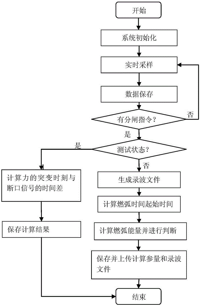
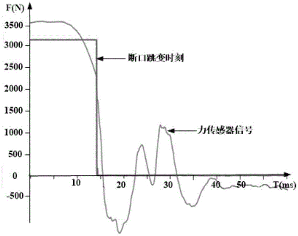
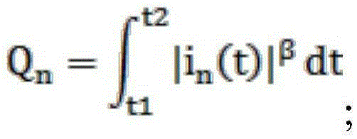
The invention provides a monitoring method for electrical endurance of an arc-extinguishing chamber of a circuit breaker and a determination method for initial time of an arcing current, wherein the method have advantages of good adaptability, simple operation and precise determination. According to the invention, when an arc-extinguishing chamber is driven by a switchgear drive system to make motion, a force value of the drive system is reduced suddenly at time of separation of a static contact and a moving contact of the arc-extinguishing chamber, wherein the sudden reduction time of the force value is the separation starting time of the arc-extinguishing chamber. Therefore, the sudden reduction time of the force value can reflect the separation starting time of the arc-extinguishing chamber. However, because an intelligent electronic device needs to carry out amplification, processing, and analyses on the collected force signal, certain hardware and software delay exists, the sudden reduction time of the force value of intelligent electronic calculation can be corrected by using an actual breaking signal, thereby determining the hardware and software delay. On the basis of real-time monitoring and recording on a force value signal and a line current signal of the drive system of the circuit breaker, the initial arcing time, arcing duration time, and arcing current value during the cut-off process of the circuit breaker are determined.

Description

technical field [0001] The invention relates to the field of measurement and monitoring of electric power systems, in particular to a method for monitoring the electrical life of an arc-extinguishing chamber of a circuit breaker and a method for judging the initial moment of arcing current. Background technique [0002] Due to the widespread application of vacuum circuit breakers in distribution networks, it is essential to monitor and judge the life of vacuum circuit breakers in order to truly achieve less maintenance and fewer accidents. The life parameters of vacuum circuit breakers are generally divided into three aspects: mechanical life, storage life and electrical life. The mechanical life of vacuum circuit breakers can generally reach 10,000 to 100,000 times; the storage life of vacuum circuit breakers that meet national standards is as long as 15 to 20 years. In general applications, what really determines the service life of a vacuum circuit breaker is its electri...

Claims


Application Information

Patent Timeline
Patent Type & Authority Applications(China)
IPC IPC(8): G01R31/327
CPCG01R31/3271
Inventor 戴冬云骆虎殷晓刚喻冬梅王瑜
Owner CHINA XIDIAN GRP CO LTD
Why Eureka
Try Eureka