Charging device with parking lock function

A technology for charging devices and parking locks, applied in circuit devices, battery circuit devices, electric vehicle charging technology, etc., can solve problems such as high failure of charging pile equipment, damage to safety, single function of charging piles, etc., to improve reliability and safety The effects of safety, accident prevention, and convenient charging operation

Inactive Publication Date: 2016-03-23
焦力波
View PDF7 Cites 47 Cited by
  • Summary
  • Abstract
  • Description
  • Claims
  • Application Information

AI Technical Summary

Problems solved by technology

[0007] 2) According to the online survey, the property owner is opposed to the introduction of charging piles into the community, on the grounds that the widespread use of electric vehicles will greatly increase the power consumption of the power grid, causing damage to the existing power grid and causing potential safety hazards
The existing charging piles belong to strong electricity operation, and installing them in the community will cause electric shock damage to children and pets
[0008] 3) Since electric vehicles belong to the primary stage of the market, the charging infrastructure is still being built and improved. The locations of the existing charging piles are scattered, and the charging pile equipment is also prone to failure.
[0009] 4) At present, charging piles generally provide fixed power charging, and cannot communicate with grid equipment
Inconvenience to the popularization of charging piles
[0010] 5) The cost of charging piles is high, the function is single, and the profit model is poor
At present, electric vehicles have just begun to popularize. Because the charging piles have single functions, the operating companies can only idle them after installing a large number of charging piles, which takes up a lot of money. This is why most charging pile operating companies take the initiative to build charging stations instead of building large quantities of them in communities or units. The reason for the charging pile

Method used


Image

  • Charging device with parking lock function
  • Charging device with parking lock function
  • Charging device with parking lock function

Examples


Embodiment

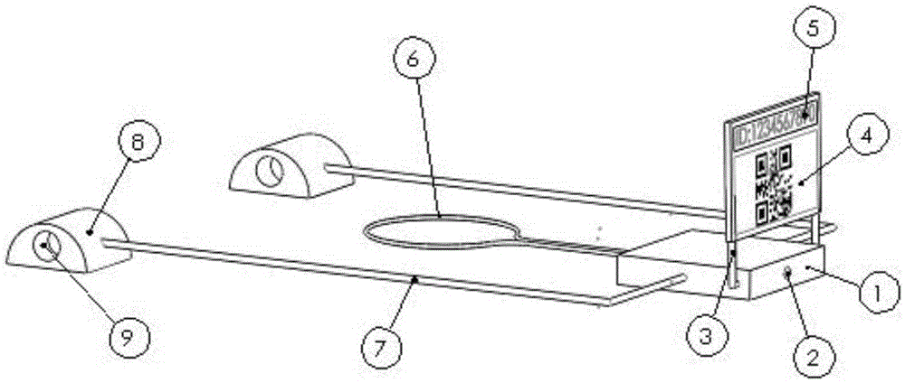
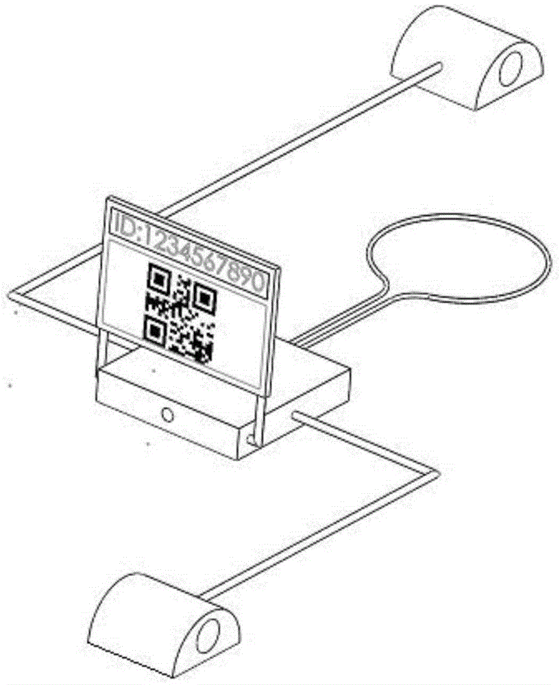
[0074] In this device, the control box 1 is installed at the front of the parking space to better protect the parking space from being occupied. The car stopper 8 is installed at the rear of the parking space. The car stopper 8 and the control box 1 are connected through the wire 7, and the wire 7 is buried in the parking space. under the ground. Due to the complex situation during the use of this device, the following description is divided into different scenarios according to the user's usage. In this embodiment, the control module is realized by a microcontroller (MCU).

[0075] 1) Scenario 1: The fixed parking space user uses the parking lock function

[0076] When the user drives the electric car close to the effective distance of wireless tag communication, the MCU receives the tag signal through the tag receiver, and after verification by the MCU, it sends an unlock command to the drive module, and the drive module drives the parking lock to block the car through the ...


PUM


Abstract

The invention relates to a charging device with a parking lock function. A control box is internally provided with a charging module, a driving module, a power module and a control module; the charging module, the driving module and the power module are all connected with the control module; the control box is provided with an AC power interface; power is provided for the power module via the AC power interface; the power module transmits power to the driving module, the control module and the charging module respectively for providing charging power and working power; the driving module is connected with the control module and the parking lock for receiving a parking lock control command sent by the control module and driving the parking lock to be locked or unlocked according to the parking lock control command; and a charging interface is arranged on a stop block, the charging interface is connected with an electric vehicle via a power line, the charging module receives a charging control command sent by the control module, and the charging module realizes wired charging on the electric vehicle according to the charging control command and/or realizes wireless charging on the electric vehicle via a wireless charging coil.

Description

technical field [0001] The invention relates to the technical field of charging devices, in particular to a charging device with a parking lock function. Background technique [0002] In September 2014, new energy vehicles were included in the national strategy. By analyzing the development of electric vehicles in pilot cities, it was found that charging electric vehicles is the biggest bottleneck restricting the development of electric vehicles. The electrification of vehicles is the future development trend, and the convenience of charging is one of the important factors for the popularization of electric vehicles. [0003] At present, there are two main ways to charge electric vehicles, one is to build special charging stations; the other is to install charging piles on parking spaces. Specialized charging stations generally provide DC fast charging, and it takes about 1 hour to fully charge an electric vehicle. Frequent use of fast charging will also damage the recharg...

Claims


Application Information

Patent Timeline
Patent Type & Authority Applications(China)
IPC IPC(8): H02J7/02B60L11/18E01F13/04E04H6/42
CPCB60L53/31E01F13/042E04H6/42H02J7/02H02J7/025B60L53/12Y02T10/70Y02T10/7072Y02T90/12Y02T90/14
Inventor 焦力波
Owner 焦力波
Why Eureka
Try Eureka