Atomizer and electronic smoking device

A technology for nebulizers and power supply devices, applied in electric heating devices, nebulizers for treatment, transportation and packaging, etc., which can solve problems such as inability to realize automatic production, shortened service life of nebulizers, and uneven heating of e-liquid , to avoid uneven heating, prevent internal pressure increase, prevent heat loss or heat conduction

Pending Publication Date: 2016-03-30
SHENZHEN FIRST UNION TECH CO LTD
View PDF9 Cites 30 Cited by
  • Summary
  • Abstract
  • Description
  • Claims
  • Application Information

AI Technical Summary

Problems solved by technology

However, the structure of the above-mentioned atomizer can only be applied to low-power atomizers, and many problems will arise when it is applied to high-power atomizers.
For example, the heating wire needs to be wound on the glass fiber core during assembly, which is difficult to assemble, has a low yield rate, and cannot realize automatic production.
Moreover, the gap between the heating wire and the surface of the glass fiber core is different during assembly, resulting in uneven heating of the smoke liquid on the surface of the glass fiber core. The heating wire may produce a burnt smell due to high temperature under the condition of high-power heating, which will cause the atomizer The service life is reduced, and there are also factors that are not conducive to health
Another example is that the heating wire and the glass fiber core are located in the same area as the liquid storage chamber. Under high power, the high temperature generated by the heating wire will cause heat conduction, and the internal pressure in the liquid storage chamber will increase, thereby increasing the risk of liquid leakage. The nozzle will be overheated due to high temperature conduction and the nozzle will be scalded

Method used


Image

  • Atomizer and electronic smoking device
  • Atomizer and electronic smoking device
  • Atomizer and electronic smoking device

Examples


Embodiment Construction

[0026] In the following, specific embodiments will be used to further illustrate the structure and principle of use of the atomizer and electronic smoking device of the present invention.

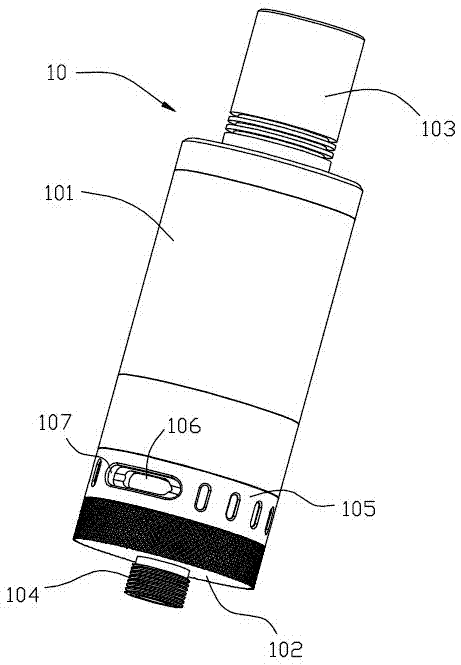
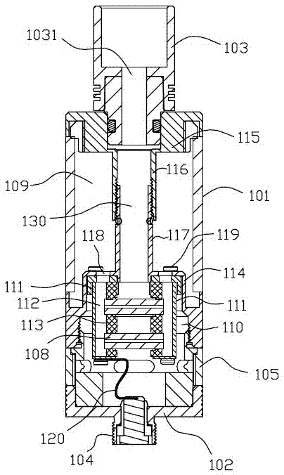
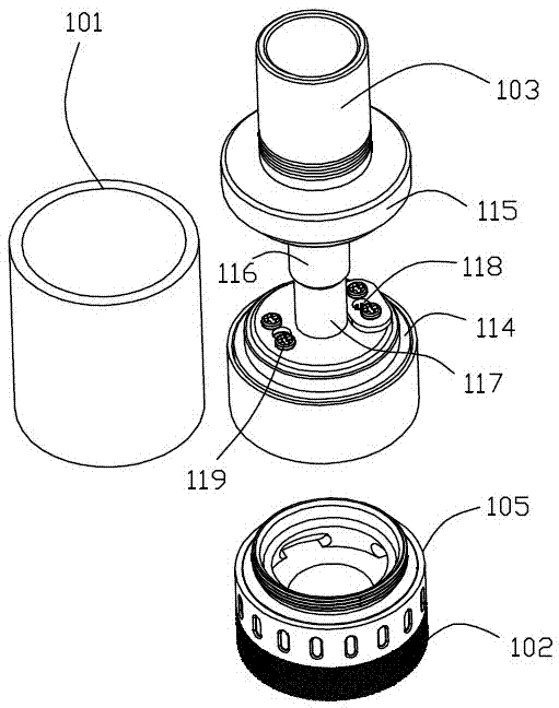
[0027] See figure 1 As shown, this embodiment provides an atomizer 10, which is generally cylindrical in appearance, including a housing 101, suction nozzles 103 and conductive parts 102 arranged at both ends of the housing 101, and threaded parts are provided on the conductive parts 102. 104. It is used to connect a power supply device to power the atomizer 10. The housing 101 is provided with a liquid storage cavity for containing the e-liquid and a heating element for heating the e-liquid, which will be described in detail later. The middle section of the housing 101 is made of transparent material, such as glass or transparent plastic, to facilitate observation and storage. The condition of the smoke liquid in the liquid cavity. An air inlet 106 is provided on the housing 101, and an adju...


PUM


Abstract

The invention discloses an atomizer and an electronic smoking device. The atomizer comprises a shell, an electric conduction part arranged on the shell and a suction nozzle with a gas outlet, a liquid storage cavity used for containing tobacco liquid is formed in the interior of the shell, the shell is further internally provided with at least one heating element which is electrically connected with the electric conduction part, each heating element comprises a liquid conduction carrier with a micropore structure and a heating part which forms an integral structure with the liquid conduction carrier, and the liquid conduction carrier can make contact with the tobacco liquid; the heating elements heat and atomize the tobacco liquid sucked by the liquid conduction carrier through the capillary action. The heating elements in the atomizer have the functions of sucking the tobacco liquid and heating simultaneously, and the atomizer is simple in structure and capable of being applied to high-power electronic smoking devices.

Description

Technical field [0001] The invention relates to the field of electronic cigarettes, in particular to an atomizer and an electronic smoking device using the atomizer. Background technique [0002] As a non-combustion simulated smoking device, electronic cigarettes can reduce the harm to the human body compared to traditional cigarettes, and have gradually been accepted by consumers. At present, in a typical atomizer used for electronic cigarettes in the prior art, the core atomization component mainly includes a liquid guide and a heating wire wound on the liquid guide. The liquid guide is generally used to absorb the liquid The glass fiber core, the liquid storage cavity used to store the smoke liquid is arranged around the glass fiber core and the heating wire. The above-mentioned atomizer relies on the glass fiber core to absorb the nicotine liquid, and uses the heating wire wound on the glass fiber core to heat the nicotine liquid to vaporize and atomize the nicotine liquid t...

Claims


Application Information

Patent Timeline
Patent Type & Authority Applications(China)
IPC IPC(8): A24F47/00A24F40/10A24F40/44A24F40/46
CPCA24F40/44A24F40/46A24F40/10B22F10/10B22F2999/00B22F1/054B22F3/1121A61M15/06A61M11/042A61M15/002H05B3/04H05B3/44H05B2203/014H05B2203/021H05B2203/022B22F3/11B22F7/06C04B38/00C22C1/1084B22F2998/10Y02P10/25
Inventor 李永海徐中立胡书云
Owner SHENZHEN FIRST UNION TECH CO LTD
Why Eureka
Try Eureka