
Locomotive wheel CNC turning repair equipment

A locomotive wheel and equipment technology, which is applied in the field of locomotive maintenance and locomotive wheel set maintenance, can solve the problems of insufficient machining accuracy, high investment cost, and difficulty in positioning and alignment, and achieve high machining accuracy, low investment cost, and structural integrity. Simple operation effect

Active Publication Date: 2017-09-22
JINAN WUXING ELECTROMECHANICAL TECH CO LTD
View PDF5 Cites 1 Cited by
  • Summary
  • Abstract
  • Description
  • Claims
  • Application Information

AI Technical Summary

Problems solved by technology

The investment cost of the equipment is high, the positioning is difficult to find, and the processing accuracy is insufficient

Method used


Image

  • Locomotive wheel CNC turning repair equipment
  • Locomotive wheel CNC turning repair equipment
  • Locomotive wheel CNC turning repair equipment

Examples


Embodiment Construction

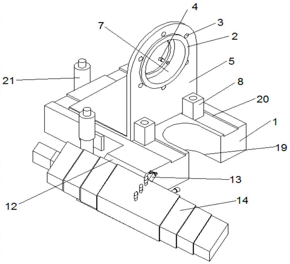
[0024]Below, take a kind of non-locomotive own power drive and be used for DF4DH4347 internal combustion locomotive, the locomotive wheel of JM3 tread rim curve as an example (1050 millimeter locomotive wheel diameter), introduce its technical scheme in detail.

[0025] Key parameters of each main component:

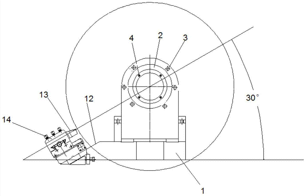
[0026] Machine base: length 1293mm, width 825mm, height 292mm; "U" opening width 180mm, depth 200mm, set in the center along the width direction of the machine base; slideway width 215mm; the inclination angle of the inclined surface 2 of the knife table installation surface 30 degrees;

[0027] Positioning bending plate: length 350mm, width 375mm, center height 464mm;

[0028] Support pile: 60*60*180mm square column;

[0029] The drive system includes: GS112M-4 motor; XWD7-87 reducer (speed ratio: 1:87);

[0030] The functions of CNC machining system include servo motor: ISMS1-40B30CB-U231Z (power: 400 watts, speed: 0-3000RPM, frequency: 50Hz); CNC box: FM-CNC208 dual...


PUM


Abstract

The invention relates to the technical field of railway equipment. A manufacturing unit and a support unit are integrated onto the same supporting platform by utilizing a pair of engine bases. The locomotive wheel numerical control lathing device provided by the invention is characterized in that a tool supporting structure, a shaft end positioning device and a shaft end supporting device are arranged on the same platform base (1), the shaft end positioning device comprises a positioning bending plate (5) and a connection plate (6) which are provided with a positioning boss (2), a mounting bolt hole (3) and an axial clearance adjustment bolt (4), and a concentric stepped hole (7) is arranged in the positioning boss (2); the positioning bending plate (5) is lengthways fixed on the platform base (1) along the center line of the rounded positioning boss (2); the tool supporting structure is of an inclined plane (12) formed by forward extended one side of the front end of the platform base (1), wherein the inclined plane (12) is parallel to a plane formed by the axial line of the positioning boss (2) and the radius of a working point. The device is light in weight, simple in structure and operation, high in working efficiency, and low in investment cost, is applied to locomotive wheel lathing operation in a railway locomotive department, and is particularly applied to the wheel lathing operation without the wheel lathing condition.

Description

Technical field [0001] The invention belongs to the technical field of railway equipment, and relates to locomotive vehicle maintenance technology, in particular to the locomotive vehicle wheel set maintenance technology. Background technique [0002] As the running part of the rolling stock, the wear and tear of the wheel and track is inevitable. In order to ensure the safe operation of the rolling stock, it is very necessary to repair the wheel rim and tread in time according to the railway industry standard. Most of the existing repair equipment is to install a large fixed CNC non-falling wheel turning bed in the maintenance ditch of the locomotive and rolling stock. There is a movable track above the turning track, and axle box supporting devices and wheel set driving devices on both sides of the moving track. . When repairing, the locomotive drives to the top, and when the wheelset to be repaired travels directly above the processing tool, the axle box supporting devic...

Claims


Application Information

Patent Timeline
Patent Type & Authority Patents(China)
IPC IPC(8): B23D79/00
CPCB23D79/00
Inventor 王广宇
Owner JINAN WUXING ELECTROMECHANICAL TECH CO LTD
Learn More