An automatic straightening mechanism used on a bushing press-in machine

A press-in machine and automatic technology, applied in the field of press-fitting machines, can solve the problems of inaccurate press-fitting position of bushings, lower production efficiency, and low pressure, and achieve improved product qualification rate, simple structure, and increased pressure. Effect

Active Publication Date: 2018-02-13
BOZHON PRECISION IND TECH CO LTD
View PDF1 Cites 0 Cited by
  • Summary
  • Abstract
  • Description
  • Claims
  • Application Information

AI Technical Summary

Problems solved by technology

However, according to the applicant's reflection, although the cylinder joint can realize compensation for the coaxiality deviation between the cylinder and the used device during use, there are still some deficiencies: the circular boss of the upper joint of the cylinder joint is set In the wide groove of the lower joint, there is an arc-shaped contact between its circumference and the wide groove, so as to realize automatic compensation for the coaxiality deviation between the cylinder and the used device, and the end surface of the circular boss and the wide groove of the lower joint Due to the stress fit between the two, when the cylinder drives the cylinder joint down, there will still be a misalignment between the upper joint and the lower joint, resulting in a certain angle deviation when the lower joint is pressed down vertically, and there will be a The pressing position of the bushing is not accurate, the pressure is small, the scrap rate is high, and the production efficiency is reduced

Method used


Image

  • An automatic straightening mechanism used on a bushing press-in machine
  • An automatic straightening mechanism used on a bushing press-in machine
  • An automatic straightening mechanism used on a bushing press-in machine

Examples


Embodiment 1

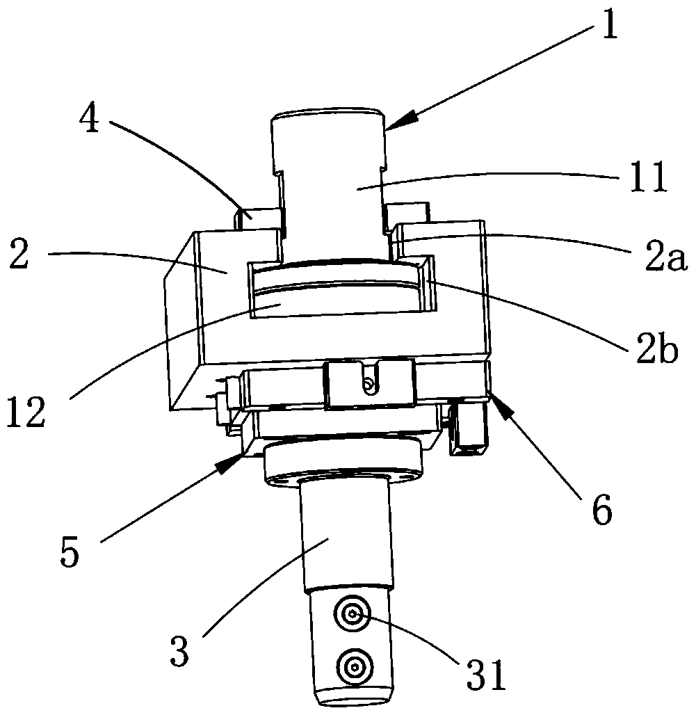
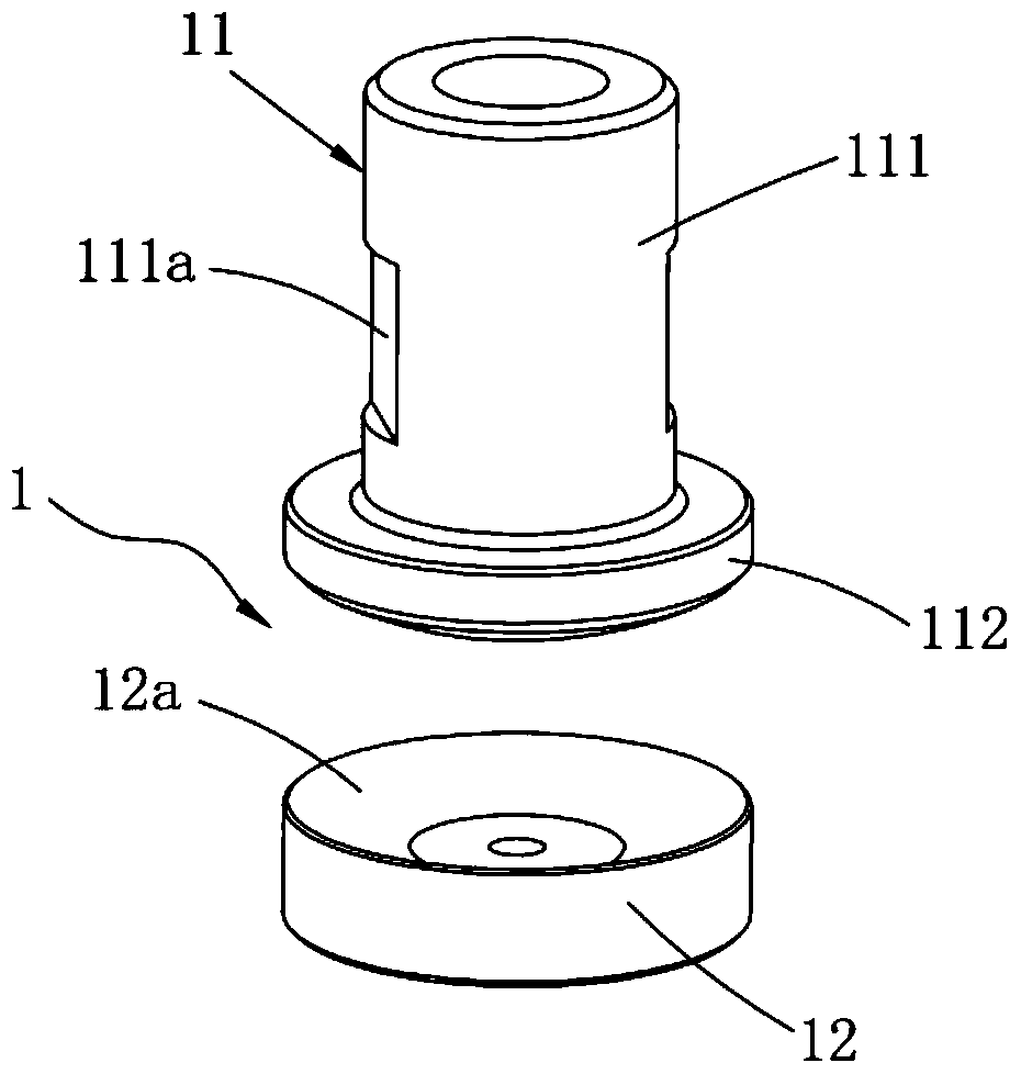
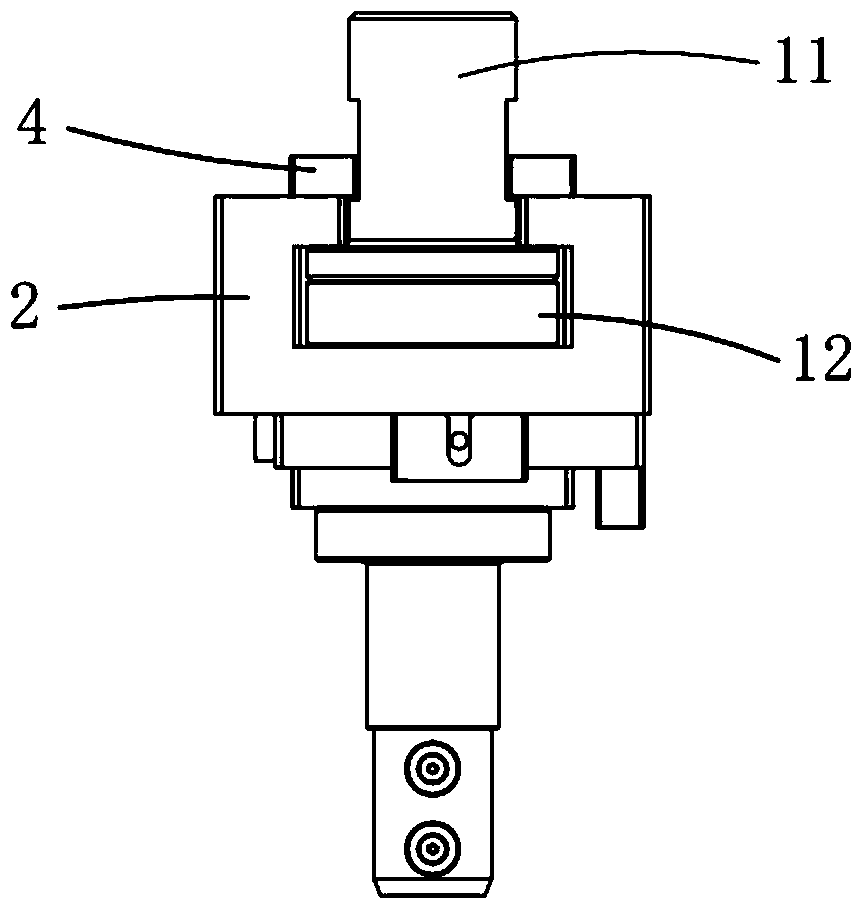
[0025] Such as figure 1 with figure 2 As shown, the present invention provides an automatic guiding mechanism for a bushing press-in machine, comprising a cylinder joint 1, a cylinder connection block 2 and a pressure head 3, and the cylinder connection block 2 is symmetrically located on both sides of the cylinder joint 1, and the cylinder The connection block 2 is provided with a narrow groove 2a and a wide groove 2b from top to bottom; the cylinder joint 1 includes an upper joint 11 and a lower joint 12, the upper joint 11 is fixedly connected with the piston rod of the cylinder, and the lower joint 12 is arranged on the cylinder. On the connection block 2, the upper joint 11 is provided with a cylindrical part 111 and an arc boss 112 in sequence from top to bottom, and an arc groove matching the arc boss 112 is processed on the upper end surface of the lower joint 12 12a, the cylindrical part 111 of the upper joint 11 is placed in the narrow groove 2a, and the lower join...


PUM


Abstract

The invention relates to an automatic alignment mechanism for a bushing press. The automatic alignment mechanism comprises an air cylinder joint, an air cylinder connecting block and a pressing head, wherein the air cylinder connecting block is symmetrically positioned at the two sides of the air cylinder joint, and is sequentially provided with a narrow groove and a wide groove from the top down; the air cylinder joint comprises an upper joint part and a lower joint part; the upper joint part is connected with a piston rod of an air cylinder; the lower joint part is arranged on the air cylinder connecting block; the upper joint part is sequentially provided with a cylindrical part and an arc boss from the top down; an arc groove is formed in the upper end face of the lower joint part; the cylindrical part of the upper joint part is arranged in the narrow groove; the lower joint part is arranged in the wide groove; the pressing head is connected with the lower joint part; and electromagnets are arranged on the pressing head. The automatic alignment mechanism adopts the separating designed air cylinder joint, and through the fitting between the arc surfaces of the upper joint part and the lower joint part, deviations in the front-back direction, the left-right direction and the coaxial direction during vertical pressing are compensated, so that automatic alignment is realized; with the combination of an X-axis regulating mechanism and a Y-axis regulating mechanism, the pressing position precision is ensured, and the pressure resistance of the pressing head is improved.

Description

technical field [0001] The invention relates to the technical field of press-fitting machines, in particular to an automatic guiding mechanism for bushing-pressing machines. Background technique [0002] The bushing is a ring sleeve that acts as a gasket. It is mainly used in the field of valves. It is generally mounted on the valve cover with equal pressure to protect the valve stem passing through the valve cover and has a good sealing effect. In the automatic bushing mechanism, the product reaches the designated position through the incoming material assembly line, the automatic feeding mechanism clamps the product through the clamping jaw cylinder, the rotating cylinder rotates, and the stepping motor performs a shifting action to shift the product to the product shifting positioning mechanism Above, the product displacement and positioning mechanism shifts the product to the positioning carrier through displacement and positioning, and then the bushing is discharged thr...

Claims


Application Information

Patent Timeline
Patent Type & Authority Patents(China)
IPC IPC(8): B23P19/027
CPCB23P19/027
Inventor 吕绍林陈小刚姜汉豪王洪录陈昊
Owner BOZHON PRECISION IND TECH CO LTD
Why Eureka
Try Eureka