
Novel electric truck chassis structure

A truck chassis and electric technology, applied in the substructure, electric power unit, power unit, etc., can solve problems such as limited space, poor protection performance of power batteries, short circuit, etc., achieve high energy efficiency utilization, sufficient expansion installation, and reduce cost effect

Active Publication Date: 2016-03-30
SUZHOU AUTO TECH
View PDF9 Cites 13 Cited by
  • Summary
  • Abstract
  • Description
  • Claims
  • Application Information

AI Technical Summary

Problems solved by technology

[0004] The electric truck chassis structure disclosed in the CN201420364106.5 patent is that the truck is driven by the front wheels, the engine and the transmission are located in the front axle, and the power batteries are distributed on both sides and in the middle of the first crossbeam in the middle, although a certain amount of power can be arranged battery, but the frame structure uses a large number of struts, which affects the weight of the frame and increases the weight of the body, and is suitable for front-wheel drive vehicles, but not for rear-wheel drive trucks
[0005] To sum up, in the prior art mentioned above, there are the following structural limitations: (1) The space utilization rate of the whole vehicle is poor, and it is difficult to make full use of the space on the chassis to arrange more power batteries and obtain a larger driving range; 2) All or part of the power battery is mounted on the outside of the frame, and the protection performance of the power battery is poor. When it is hit by the side, the power battery is vulnerable to collision, causing problems such as battery deformation, rupture, and electrolyte leakage. Short circuit, even fire and other major problems that affect the safe driving of the vehicle; (3) The follow-up platform has poor expandability, and if it is necessary to add accessories to the vehicle, the space is limited

Method used


Image

  • Novel electric truck chassis structure
  • Novel electric truck chassis structure

Examples


Embodiment

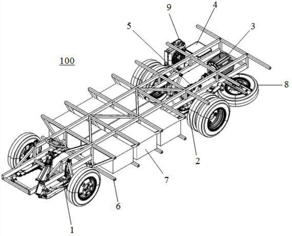
[0030] Please refer to figure 1 , the present embodiment is a novel electric truck chassis structure 100, which includes a front axle 1, a rear axle 2, a motor 3 for driving the rear axle, a motor controller 4, a speed reduction mechanism 5 with one end connected to the rear axle 2 and the other end connected to the motor 3, The truss-type vehicle frame 6 mounted on the front axle 1 and the rear axle 2 and the power battery 7 accommodated inside the vehicle frame 6 are fixed.

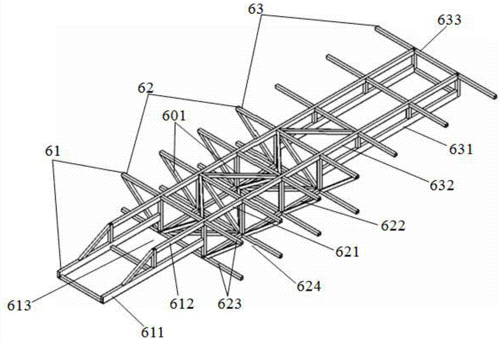
[0031] Please refer to figure 2 , the vehicle frame 6 is a mixed structure of truss and rigid frame, which is mainly formed and welded by rectangular profiles, channel profiles and angle steels.

[0032] The front frame 61 includes two first lower beams 611 fixedly erected on the front axle 1 and arranged in parallel, a first upper beam 612 positioned directly above the first lower beams 611, a first lower beam 611, a first upper beam 612 The first receiving space 613 formed by the middle frame 62 . ...


PUM


Abstract

The invention discloses a novel electric truck chassis structure which comprises a front axle, a rear axle, a motor, a truss type truck frame which is fixedly erected on the front axle and the rear axle, and power batteries contained inside the truck frame. The truck frame sequentially comprises a front frame body erected on the front axle, a middle frame body of a double-layer structure, and a tail frame body erected on the rear axle. The front frame body is provided with a first containing space used for containing the power batteries. The middle frame body comprises a plurality of second containing spaces which are penetrating in the left-right direction and a plurality of cross beams used for forming the second containing spaces. The length of each first cross beam is larger than the sum of the lengths of the two power batteries. The motor is fixed to the tail portion of the tail frame body. The power batteries are contained in the first containing space and the second containing spaces. The novel electric truck chassis structure is high in space utilization rate, large in battery capacity, and good in safety anti-collision resistance.

Description

【Technical field】 [0001] The invention belongs to the technical field of electric trucks, in particular to a novel electric truck chassis structure. 【Background technique】 [0002] With the increasing emphasis on environmental issues, the country has formulated relevant laws and policies to protect the environment. Under the general trend of environmental protection, new energy electric vehicles are also developing rapidly, and new pure electric trucks are also in the early stages of development. stage. At present, electric truck products are generally based on traditional trucks, replacing the engine with an electric motor, removing fuel-related accessories, and then mounting the power battery on both sides of the frame. [0003] In the structure of the electric truck frame assembly disclosed in the CN201420054088.0 patent, since the middle part of the frame needs to accommodate the transmission shaft, the power batteries can only be distributed on both sides of the frame,...

Claims


Application Information

Patent Timeline
IPC IPC(8): B62D21/02B60K1/04
CPCB60K1/04B60K2001/0438B62D21/02
Inventor 宿佳敏宋峰李明邓小波田永义向绍宇
Owner SUZHOU AUTO TECH
Features
  • Generate Ideas
  • Intellectual Property
  • Life Sciences
  • Materials
  • Tech Scout
  • Unparalleled Data Quality
  • Higher Quality Content
  • 60% Fewer Hallucinations
Learn More