U-shaped movable hold hoop type lifting lug for hoisting tower facility and hoisting method thereof

A U-shaped, lifting lug technology, applied in the directions of transportation and packaging, load hanging components, etc., can solve the problems of large consumption and increase of steel, and achieve the effect of low production cost, convenient use and speeding up the progress of the project.

Active Publication Date: 2016-03-30
CHINA NAT CHEM ENG THIRD CONSTR
View PDF6 Cites 9 Cited by
  • Summary
  • Abstract
  • Description
  • Claims
  • Application Information

AI Technical Summary

Problems solved by technology

For tower equipment, the lugs originally designed for hoisting the equipment body cannot be used due to the increase in the additional weight of internal parts and fillers, and the lugs must be redesigned.
Tower equipment is a chemical pressure vessel, and welding is generally prohibited on the equipment body. Even if welding lugs are allowed, processes such as heat treatment, non-destructive testing, and hydraulic testing are required after welding, and the tower wall at the welding lug must be thickened. High-altitude welding, high steel consumption

Method used


Image

  • U-shaped movable hold hoop type lifting lug for hoisting tower facility and hoisting method thereof
  • U-shaped movable hold hoop type lifting lug for hoisting tower facility and hoisting method thereof
  • U-shaped movable hold hoop type lifting lug for hoisting tower facility and hoisting method thereof

Examples


Embodiment Construction

[0028] Below in conjunction with accompanying drawing, by describing embodiment, the present invention will be further described:

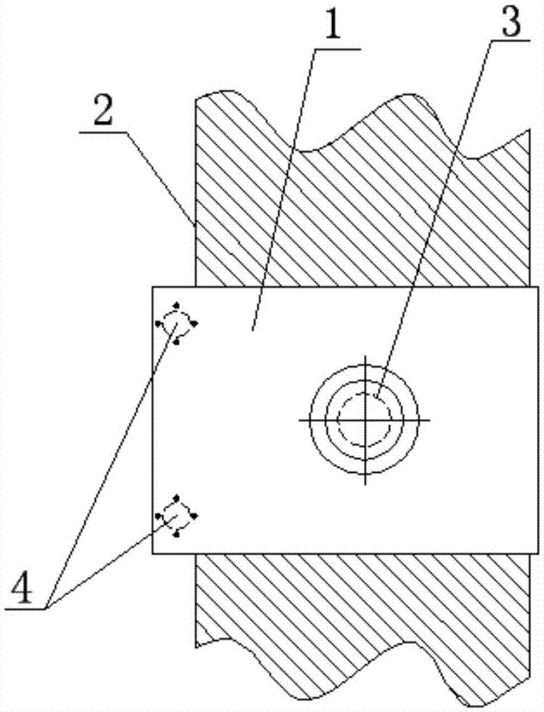
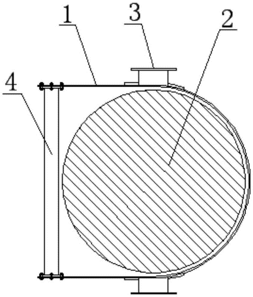
[0029] like figure 1 , 2 As shown, a U-shaped movable hoop-type lifting lug for tower equipment hoisting according to the present invention includes a U-shaped hoop 1, which is formed by bending a steel plate, and the thickness of the bent plate of the U-shaped hoop 1 is 30mm, the hoop of U-shaped hoop 1 is hooped on the side wall of tower body 2. The diameter of the tower is 2.5m, the height is 54m, and the weight is 98t. The curvature of the hoop of U-shaped hoop 1 is the same as that of the side wall of tower body 2. The curvature of the U-shaped hoop 1 is symmetrical, and a pair of tube-shaft lifting lugs 3 are symmetrically arranged on both sides of the U-shaped hoop 1. The tube-shaft lifting lugs 3 are made of steel pipes on site. It just falls on the axis connection of the two tubular lifting lugs 3. There is a reinforcing ring between th...


PUM


Abstract

The invention discloses a U-shaped movable hold hoop type lifting lug for hoisting a tower facility and a hoisting method thereof. The U-shaped movable hold hoop type lifting lug comprises a U-shaped hold hoop, wherein a hoop ring of the U-shaped hold hoop hoops the side wall of a tower body, a pair of pipe shaft type lifting lugs is symmetrically arranged on two sides of the U-shaped hold hoop, the circle center of the cross section of the side wall of the tower body is rightly located on the axis connection of the two pipe shaft type lifting lugs, connecting rods are connected between the open ends of the U-shaped hold hoop, the tower body is hooped through the U-shaped hold hoop, the pipe shaft type lifting lugs on the U-shaped hold hoop are hoisted through a sling of a main hoisting crane during hoisting, and the pipe shaft type lifting lugs are connected with auxiliary lifting lugs. Therefore, the lifting force of the sling is transferred to the auxiliary lifting lugs to avoid sliding of the U-shaped hold hoop, the sling of an auxiliary hoisting crane hoists a tail-lifting lifting lug, enables the tower body to be changed from a vertical state to a horizontal state under the cooperative effect with the main hoisting crane and enables the U-shaped hold hoop to bear the radial pressure of the tower body, and safety is ensured. The tower body is hoisted by using the U-shaped movable hold hoop type lifting lug and the hoisting method, welding operation required to be performed on the tower body is avoided, and the tower body is protected.

Description

technical field [0001] The invention relates to hoisting technology, in particular to a U-shaped movable hoop-type lifting lug for hoisting tower equipment and a hoisting method thereof. Background technique [0002] In recent years, with the development of the economy, the country has paid more and more attention to safety and environmental protection. The relocation and transformation of chemical production enterprises in and around the city is a major measure. The landmark buildings of chemical production enterprises are tower equipment. Tower equipment has the characteristics of high, large and heavy. It is the key and difficult point of the relocation and demolition of chemical equipment. In order to reduce the pollution to the interior of the equipment and reduce the intensity of manual labor in the reconstruction of chemical equipment, it is often required that the installed internal parts and fillers in the equipment are hoisted and removed together with the equipmen...

Claims


Application Information

Patent Timeline
Patent Type & Authority Applications(China)
IPC IPC(8): B66C1/10
CPCB66C1/10
Inventor 张宗斌
Owner CHINA NAT CHEM ENG THIRD CONSTR
Why Eureka
Try Eureka