Pressure control type air energy water heater and control method

A technology of air-energy water heaters and heat exchangers, which is applied in fluid heaters, heating and cooling combinations, and compressors with reversible cycles, etc. It can solve the problem that water heater functions and air-conditioning functions cannot be completely independent and increase the number of air-energy water heater failures Probability, air energy water heater operation is easy to shut down and other problems, to achieve the effect of fast heating speed, convenient switching, and reduced resistance

Inactive Publication Date: 2016-03-30
JIANGMEN THISGO TECH
View PDF7 Cites 10 Cited by
  • Summary
  • Abstract
  • Description
  • Claims
  • Application Information

AI Technical Summary

Problems solved by technology

[0002] When the existing air-energy water heater operates in multiple modes such as independent hot water, hot water and cold air, hot water and heating, independent cooling, independent heating, etc., due to the uneven pressure of the internal pipeline, it is easy to appear. The air pressure of some pipelines is too high or too low, which makes the air energy water heater easy to stop when it is running, and it is prone to failure, which increases maintenance costs and reduces service life
When the current air energy water heater realizes the functions of water heater and air conditioner at the same time, the water heater function and the air conditioner function cannot be completely independent. The water heater function can only be performed when the air conditioner function has been turned on. Only two functions can be turned on, which brings great inconvenience to the user, wastes electric energy, increases the failure rate of the air energy water heater, and reduces the service life

Method used


Image

  • Pressure control type air energy water heater and control method

Examples


Embodiment Construction

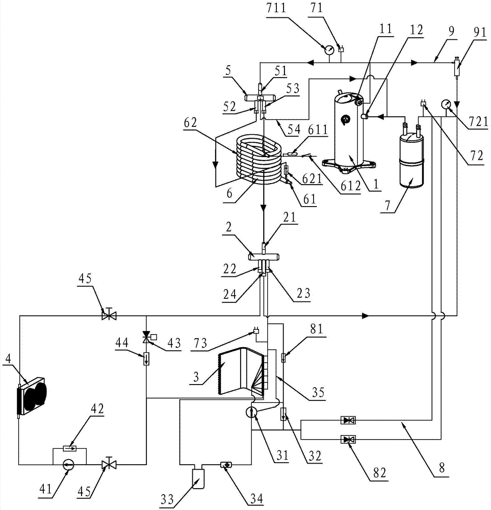
[0016] like figure 1 As shown, the arrows on the pipeline in the figure indicate the running direction of the refrigerant. In the figure, the first expansion valve 31, the second expansion valve 41, the first check valve 32, the second check valve 42, the third check valve 44, The arrows in the fourth check valve 621 and the fifth check valve 81 indicate the running direction of the refrigerant in the valve body. A pressure-controlled air energy water heater includes a compressor 1, a four-way valve 2, and a first heat exchanger. 3 and the second heat exchanger 4, the compressor 1 includes a high-pressure exhaust port 11 and a low-pressure suction port 12, the four-way valve 2 includes an A connection port 21, a B connection port 22, a C connection port 23 and a D connection port 24, The high-pressure exhaust port 11 and the low-pressure suction port 12 of the compressor 1 are respectively connected with the A connection port 21 and the D connection port 24, and the two commun...


PUM


Abstract

The invention discloses a pressure control type air energy water heater, which comprises a compressor, a four-way valve, a first heat exchanger and a second heat exchanger, wherein the compressor comprises a high-pressure air outlet and a low-pressure air inlet; the four-way valve comprises a connecting port A, a connecting port B, a connecting port C and a connecting port D; a heat exchange pipe is arranged on a pipeline between the high-pressure air outlet of the compressor and the connecting port A; and the heat exchange pipe comprises a first pipe fitting and a second pipe fitting which sleeves the first pipe fitting. A control method of the pressure control type air energy water heater is that an independent water heating mode, a water heating and air cooling mode, a water heating and air warming mode, an independent air cooling mode and an independent air warming mode are switched. The pressure control type air energy water heater and the control method have the advantages that the heating speed is rapid; electric energy is saved; the pipeline pressure is stable; and the operation is smooth and the like; and the pressure control type air energy water heater can independently operate among the water heating function, the air cooling function and the air warming function, and the three functions are freely switched and mutually combined, so convenience and practicability are realized.

Description

technical field [0001] The invention relates to a pressure-controlled air energy water heater and a control method. Background technique [0002] When the existing air-energy water heater operates in multiple modes such as independent hot water, hot water and cold air, hot water and heating, independent cooling, independent heating, etc., due to the uneven pressure of the internal pipeline, it is easy to appear. The air pressure of some pipelines is too high or too low, which makes the air source water heater easy to stop when it is running, and it is prone to failure, which increases maintenance costs and reduces service life. When the current air energy water heater realizes the functions of water heater and air conditioner at the same time, the water heater function and the air conditioner function cannot be completely independent. The water heater function can only be performed when the air conditioner function has been turned on. Only when two functions are turned on c...

Claims


Application Information

Patent Timeline
Patent Type & Authority Applications(China)
IPC IPC(8): F25B13/00F25B29/00F25B41/04F25B41/06F25B49/02F25B47/02F24H4/02F25B41/20F25B41/31
CPCF24H4/02F25B13/00F25B29/003F25B47/02F25B49/02F25B2347/02F25B2313/02731F25B2313/02741F25B41/31F25B41/20
Inventor 李绍强张玉梅周炜彬
Owner JIANGMEN THISGO TECH
Why Eureka
Try Eureka