Eureka AIR delivers breakthrough ideas for toughest innovation challenges, trusted by R&D personnel around the world.

Device and method for simulating test of pore water pressure of asphalt pavement

A technology for pore water pressure and simulation testing, which is used in measurement devices, permeability/surface area analysis, suspension and porous material analysis, etc. The effect of easy opening and closing, increased test frequency, and reduced inflation

Inactive Publication Date: 2016-03-30
广州市和富市政工程有限公司
View PDF12 Cites 4 Cited by
  • Summary
  • Abstract
  • Description
  • Claims
  • Application Information

AI Technical Summary

Problems solved by technology

[0004] In the indoor simulation test, if the test method including the loading method is not designed, especially if the drainage conditions of the specimen boundary are not limited, it will not meet the special flow law of pore water in the porous area of ​​asphalt pavement; The pore water pressure response is directly related, and the inconsistency between the simulated test and the actual pore water flow on the pavement will lead to a large difference between the pore water pressure and the pavement site

Method used


Image

  • Device and method for simulating test of pore water pressure of asphalt pavement
  • Device and method for simulating test of pore water pressure of asphalt pavement
  • Device and method for simulating test of pore water pressure of asphalt pavement

Examples


Embodiment 1

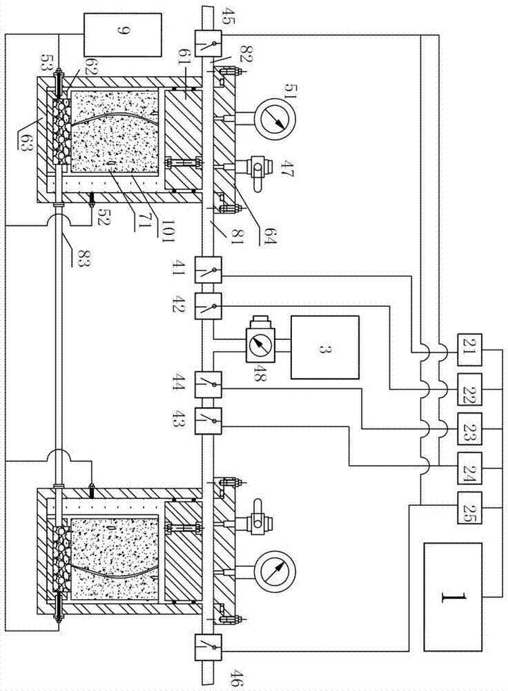
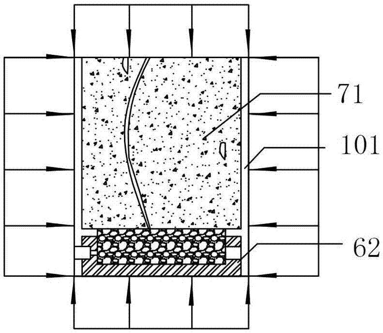
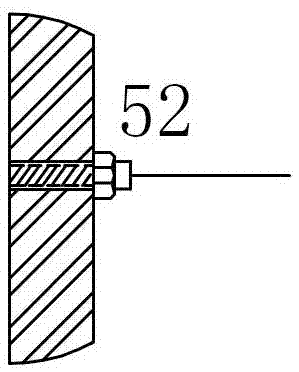
[0045] like Figure 1~4 Shown, a kind of asphalt pavement pore water pressure simulation testing device comprises at least two pressure vessels 63, and each pressure vessel 63 is provided with asphalt concrete specimen 71, open container 62, the bottom of asphalt concrete specimen 71 and the opening Adhesive 101 is filled between the opening annular parts of container 62 (adhesive 101 in this embodiment is specifically epoxy resin, phenolic resin can achieve the same technical effect), and the side wall of asphalt concrete specimen 71 is coated with adhesive agent 101; the lower part of the side wall of the open container 62 is symmetrically provided with two mounting holes, one of which is provided with a first pressure sensor 52 for measuring the external water pressure of the asphalt concrete specimen 71, and the other mounting hole is provided with a The second pressure sensor 53 for measuring the water pressure at the bottom of the asphalt concrete test piece 71;

[0046...

Embodiment 2

[0058] like Figure 5 As shown, the specific process of the method for testing using the device described in Embodiment 1 is as follows:

[0059] (1) Asphalt concrete specimens 71 with a diameter not less than 100mm and not more than 155mm obtained by indoor preparation or on-site core drilling on the road surface;

[0060] (2) Fill the cylindrical open container 62 with the same outer diameter as the asphalt concrete specimen 71 and with a sensor installation hole on one side with the crushed stones sieved by a standard square hole sieve of 13.2 mm to 16 mm, and then fill it with water;

[0061] (3) Glue the bottom of the asphalt concrete specimen 71 and the top open circular part of the cylindrical open container 62 filled with gravel with adhesive 101, and coat the circumference of the side wall of the asphalt concrete specimen 71 with adhesive 101 And make it flow naturally until the adhesive 101 is coated on the outer sidewall of the asphalt concrete specimen 71 and the ...

Embodiment 3

[0073] The specific process of the method for testing using the device described in Embodiment 1 is the same as in Embodiment 2, except that the control process adopted in this embodiment is as follows:

[0074] The first air intake control valve 41 is controlled by the programmable controller 1 to open for 0.25s, and the second air intake control valve 42 is opened for 0.25s at 0.15s. Apply pressure to the asphalt concrete specimen 71 within 0.1s when the gas control valve 42 is opened at the same time; at 0.25s, the first exhaust control valve 45 is opened for 0.25s to exhaust the pressure vessel 63 to atmospheric pressure; at 0.1s, the fourth The air intake control valve 44 is opened for 0.25s, and the third air intake control valve 43 is opened for 0.25s at 0.25s; the second exhaust control valve 46 is opened for 0.3s at 0.35s to exhaust the pressure vessel 66 to atmospheric pressure; except for the second exhaust control valve 46 at an interval of 0.1s, the other control ...


PUM


Abstract

The invention discloses a device and a method for simulating a test of pore water pressure of an asphalt pavement. The device comprises at least two pressure containers, wherein a binder is filled between the bottom part of an asphalt concrete specimen in each pressure container and an opening annular part of an opening container; the side wall of each specimen is coated with a sealing part; a first pressure sensor is arranged at the side wall of each pressure container and is used for testing the external water pressure of the corresponding specimen; a second pressure sensor is arranged at the side wall of each opening container and is used for testing the bottom water pressure of the corresponding specimen; the opening containers are communicated by a pipeline which penetrates through the side walls of the pressure containers. The method has the advantages that by adopting a control process meeting different wheel load functions and characteristics, the specimens in the pressure containers are successively and respectively loaded, the internal and external water pressures of each specimen are effectively sealed and isolated, and the external water pressure and pore water pressure during loading are monitored in real time. The device has the advantages that the directional flowing of pore water is realized, and a dynamic response rule of the pore water pressure of asphalt concrete under the action of dynamically-changed external water pressure can be tested.

Description

technical field [0001] The invention relates to dynamic water pressure analysis of asphalt pavement, in particular to a pore water pressure simulation test device and method at the bottom of an asphalt layer of asphalt pavement. Background technique [0002] Patents CN101216401B, CN101210870B, CN102253187B, US8312776, and US6799471B1 proposed methods or devices for causing pore water flow in asphalt concrete specimens by applying external water pressure, but none of them monitored the caused pore water pressure of asphalt concrete. Water flows non-directionally, and some simulation tests also have the problem of low loading speed. [0003] For the point-shaped porous area on the asphalt pavement whose planar area is smaller than the tire contact area, the pavement pore water generally seeps downward under the action of the wheel load; but for the planar porous area on the asphalt pavement whose planar area is larger than the tire contact area, such as asphalt In the band-sh...

Claims


Application Information

Patent Timeline
Patent Type & Authority Applications(China)
IPC IPC(8): G01N15/08
CPCG01N15/08G01N15/088
Inventor 姜旺恒周兴刘志恒
Owner 广州市和富市政工程有限公司
Why Eureka
Eureka Blog
Learn More