Flow injection analysis device with exhaust function and exhaust method during flow injection analysis

A technology of flow injection and analysis device, applied in the direction of analysis materials, instruments, etc., can solve the problems of cumbersome operation, unfavorable analysis efficiency, limited application scope, etc., to ensure the defoaming effect, simplify the exhaust operation, and achieve a good exhaust effect. Effect

Inactive Publication Date: 2017-06-16
SICHUAN UNIV
View PDF6 Cites 0 Cited by
  • Summary
  • Abstract
  • Description
  • Claims
  • Application Information

AI Technical Summary

Problems solved by technology

[0003] In order to introduce as few bubbles into the flow path system as possible during flow injection analysis, the impetus liquid, chromogenic liquid, and sample solution are usually vacuumized and degassed or ultrasonically oscillated before sample injection to reduce the dissolved gas. However, this operation can only reduce the introduction of air bubbles into the flow path system, but cannot eliminate the bubbles already generated in the flow path. When the small air bubbles generated in the flow path system remain in the optical flow cell and interfere with normal detection, the operation can only be stopped. For the flow injection analysis device, take out the optical flow cell, flick the outer wall of the optical flow cell repeatedly with your fingers, and change the angle of the optical flow cell while flicking, so that the small bubbles trapped in it gradually move upward until the small bubbles are removed. After all the air is discharged, put the optical flow cell into the flow injection analysis device to continue the analysis. The operation of this method of air bubble removal is very cumbersome, which is not conducive to the improvement of analysis efficiency, and also hinders the saving of labor costs during flow injection analysis.
Li Jinxin et al. improved the existing flow injection analysis device by installing a back pressure ring behind the optical flow cell to increase the pressure of the flow path system. The increase in the pressure of the flow path system can reduce the volatilization of the solution and increase the gas flow rate. Solubility in water, thereby reducing the interference of air bubbles on analysis (Rock and Mineral Test, 1996,15(2):104-106), the improved flow injection analysis device can only reduce the release of air bubbles due to heating or the generation of air bubbles due to volatilization of the solution , but cannot eliminate the air bubbles generated in the flow path system due to other reasons, the scope of application is limited, and the back pressure ring may cause the pressure of the flow path system to be too high, resulting in damage to the flow cell

Method used


Image

  • Flow injection analysis device with exhaust function and exhaust method during flow injection analysis
  • Flow injection analysis device with exhaust function and exhaust method during flow injection analysis
  • Flow injection analysis device with exhaust function and exhaust method during flow injection analysis

Examples


Embodiment 1

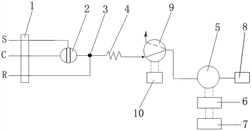
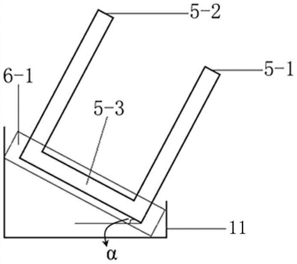
[0038] In this embodiment, the structure of the flow injection analysis device with exhaust function is as follows figure 1 As shown, it includes a low-pressure pump 1, a six-way sampling valve 2, a first mixer 3, a reactor 4, an optical flow cell 5, an optical detector 6, a computer processing system 7 and a waste liquid container 8, and the optical flow cell 5 is a U-shaped optical flow cell, including an optical detection channel 5-3, a liquid inlet channel 5-1 and a liquid outlet channel 5-2 communicated with the optical detection channel, and the optical detector 6 includes an optical system box 6-1 and an optical Signal acquisition and processing system, the optical detection channel 5-3 of the optical flow cell is installed in the optical path system box of the optical detector, the detection light path of the optical detector passes through the optical detection channel 5-3 of the optical flow cell and is connected with the optical flow cell The optical detection chann...

Embodiment 2

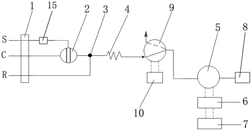
[0044] In this embodiment, the structure of the flow injection analysis device with exhaust function is as follows image 3 As shown, it includes a low-pressure pump 1, a six-way sampling valve 2, a first mixer 3, a reactor 4, an optical flow cell 5, an optical detector 6, a computer processing system 7 and a waste liquid container 8, and the optical flow cell 5 is a U-shaped optical flow cell, including an optical detection channel 5-3, a liquid inlet channel 5-1 and a liquid outlet channel 5-2 communicated with the optical detection channel, and the optical detector 6 includes an optical system box 6-1 and an optical Signal acquisition and processing system, the optical detection channel 5-3 of the optical flow cell is installed in the optical path system box of the optical detector, the detection light path of the optical detector passes through the optical detection channel 5-3 of the optical flow cell and is connected with the optical flow cell The optical detection chann...

Embodiment 3

[0049] In this embodiment, the structure of the flow injection analysis device with exhaust function is as follows Figure 5 As shown, it includes a low-pressure pump 1, a six-way sampling valve 2, a first mixer 3, a reactor 4, an optical flow cell 5, an optical detector 6, a computer processing system 7 and a waste liquid container 8, and the optical flow cell 5 is a U-shaped optical flow cell, including an optical detection channel 5-3, a liquid inlet channel 5-1 and a liquid outlet channel 5-2 communicated with the optical detection channel, and the optical detector 6 includes an optical system box 6-1 and an optical Signal acquisition and processing system, the optical detection channel 5-3 of the optical flow cell is installed in the optical path system box of the optical detector, the detection light path of the optical detector passes through the optical detection channel 5-3 of the optical flow cell and is connected with the optical flow cell The optical detection chan...


PUM


Abstract

The invention provides a flow injection analysis apparatus with exhausting function. The apparatus comprises a low pressure pump, a six-way injection valve, a first mixer, a reactor, an optical flow cell, an optical detector, a computer processing system, a waste liquid container, a solenoid valve and a time relay which is matched with the solenoid valve. The invention also provides an exhausting method for flow injection analysis; the method is used for the flow injection analysis apparatus with exhausting function, and can be used for realizing hand-operated exhaust or automatic on-line exhaust during the flow injection analysis process; the exhaust operation is simple, the exhaust effect is good, and the analysis efficiency is improved.

Description

technical field [0001] The invention belongs to the field of flow injection analysis, in particular to a flow injection analysis device with exhaust function and an exhaust method during flow injection analysis. Background technique [0002] During flow injection analysis (FIA), the sample or standard sample is injected into the reagent carrier flow in the pipeline in the form of a sample plug for analysis and testing. During the flow injection analysis process, due to the poor airtightness of the joints of the flow path system, the poor sealing degree of the valve, and the use of a peristaltic pump to feed the liquid, it is easy to suck air bubbles from the outside of the flow path system, or due to the Heating is required, causing the solubility of the gas in the sample or standard sample solution and the carrier to decrease, releasing bubbles or the liquid in the flow system evaporates to form bubbles, and the unstable decomposition of the reagent produces bubbles, the re...

Claims


Application Information

Patent Timeline
Patent Type & Authority Patents(China)
IPC IPC(8): G01N35/08
CPCG01N35/085
Inventor 张新申莫珊高跃昕赵正喜杜永华
Owner SICHUAN UNIV
Why Eureka
Try Eureka