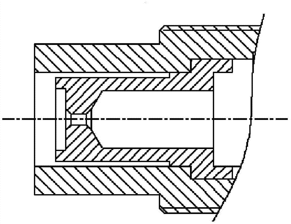
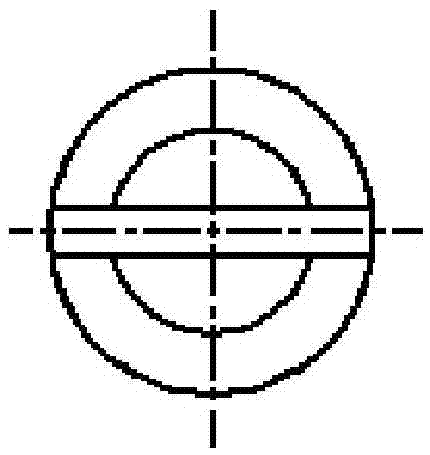
Mini-type non-cooling plasma jet igniter

A plasma, non-cooling technology

Active Publication Date: 2016-03-30
XIAN AEROSPACE PROPULSION INST
View PDF7 Cites 5 Cited by
  • Summary
  • Abstract
  • Description
  • Claims
  • Application Information

AI Technical Summary

Problems solved by technology

However, conventional plasma igniters have shortcomings and deficiencies in terms of airborne assembly, portability, and reliability.

Method used


Image

  • Mini-type non-cooling plasma jet igniter
  • Mini-type non-cooling plasma jet igniter
  • Mini-type non-cooling plasma jet igniter

Examples


Embodiment Construction

[0030] As shown in FIG. 3, the small uncooled plasma jet igniter of the present invention includes a cathode 3, an anode 1, a cyclone 2, a casing, an anode terminal 5, a cathode terminal 6, a spring 12, a cathode terminal rod 4 and The ceramic ring 8, the tail of the anode 1 is provided with a blind hole 15, the inner wall of the tail of the anode 1 is provided with a first inner ring groove 20; the cathode 3 includes a cathode head, a middle part and a cathode tail, and the diameter of the middle of the cathode is larger than that of the head and tail. The outer wall of the front end of the middle of the cathode is provided with a first annular shoulder 16; the outer wall of the cathode tail is provided with a second annular shoulder 17, the end of the cathode tail is provided with a through slot 18 inward, and the center of the cathode connecting rod is provided with an air channel The cathode terminal is divided into a cathode terminal head and a cathode terminal tail, the d...


PUM


Abstract

The invention provides a mini-type non-cooling plasma jet igniter which mainly comprises an anode, a cathode, a whirlcone, ceramic parts, a shell, a spring, and an air supply pipeline (cathode connection pipe), wherein parts such as the anode, the cathode and the ceramic parts are pressed and fixed via the shell and the spring; and the cathode is in plug-in connection with the cathode connection pipe. The mini-type non-cooling plasma jet igniter has the advantages that the size is small; the weight is light; the use is convenient; the mounting and the maintenance are simple; the ignition capability is high; and repeated ignition can be realized. The mini-type non-cooling plasma jet igniter can serve as an ignition device for various heaters, combustion chambers, aero-engines and ATR combined engines.

Description

technical field [0001] The invention relates to a plasma jet igniter. Background technique [0002] At present, the ignition devices of aero-engines and ATR combined engines are mostly electric squibs, ignition agents, and spark plugs. Electric squib and ignition agent ignition have the disadvantages of poor safety and difficult to achieve multiple starts, while ordinary spark plug ignition has the disadvantages of low ignition energy and general ignition reliability. Plasma ignition technology is an effective way to improve the ignition reliability of aero-engines and ATR combined engines, and to achieve multiple ignition and reuse functions. However, conventional plasma igniters have shortcomings and deficiencies in on-board assembly, portability, and reliability. SUMMARY OF THE INVENTION [0003] The invention overcomes the shortcomings and deficiencies of the existing plasma ignition technology in terms of assembly, portability and reliability, and provides a small u...

Claims


Application Information

Patent Timeline
Patent Type & Authority Applications(China)
IPC IPC(8): H01T13/02H01T13/20
CPCH01T13/02H01T13/20
Inventor 王飞王妍魏建国韩先伟狄江逯婉若张蒙正
Owner XIAN AEROSPACE PROPULSION INST
Why Eureka
Try Eureka