A multifunctional health-care electric mattress and a double-rocker double-position driving mechanism
A multi-functional, electric technology, applied in the direction of beds, other seating furniture, sofas, etc., can solve the problems of incomplete function, unstable back rise, etc., and achieve the effect of simple structure, suitable for home installation, and simple driving structure
- Summary
- Abstract
- Description
- Claims
- Application Information
AI Technical Summary
Problems solved by technology
Method used
Image
Examples
Embodiment 1
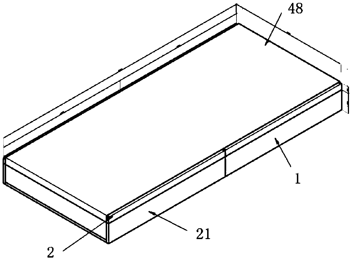
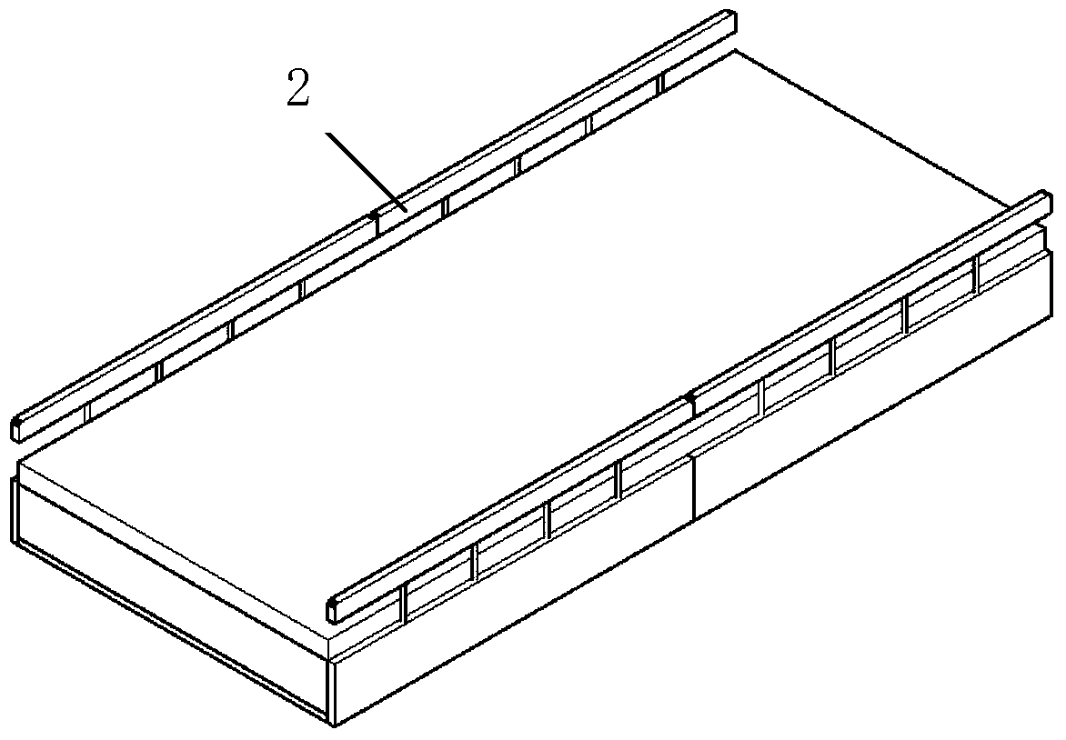
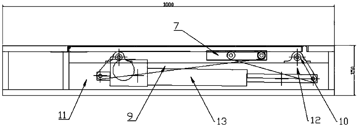
[0034] Example 1: Combining Figure 1 to Figure 4, a multifunctional health care electric mattress, comprising an upper box body 1 and a lower box body 21 connected by hinges, a cushion part 48 laid on the upper box body 1 and the lower box body 21, and the upper box body 1 is installed There are first movable plate 3, second movable plate 4 and third movable plate 5, the second movable plate is hinged with the box body, between the first movable plate 3 and the second movable plate 4, between the second movable plate 4 and the third movable plate The movable plates 5 are respectively connected with spring leaf 20, and two beams 11 are arranged in the upper box body, and an upper electric push-pull rod 13 is installed on the base between the two beams 11, and a small The rocker arm group 12 and the large rocker arm group 9, and the small rocker arm group 12 are located in front of the upper electric push-pull rod, and the large rocker arm group 9 is located at the rear of the ...
Embodiment 2
[0040] Embodiment 2: Based on the above-mentioned embodiment, in combination with Figure 8 to Figure 12 , the present invention can also be: a small movable plate 28 is hinged on the lower box body 21, a large movable plate 27 connected with the small movable plate 28, two groups of rocker arm assemblies 30 and 25 are arranged in the lower box body, the first group The rocker arm assembly 30 is positioned at the small movable plate 28 below, and the second group of rocker arm assemblies 25 is positioned at the large movable plate 27 below, and each group of rocker arm assemblies includes hingedly mounted on the stressed square steel (or aluminum profile) 24 in the lower casing. Two rocking arms, the third connecting rod 46 is arranged between the two rocking arms of the first group, and the fourth connecting rod 47 is arranged between the two rocking arms of the second group (the principle is the same as that of the large rocking arm group and the large rocking arm group in th...
Embodiment 3
[0047] Embodiment three: based on the above embodiment, in combination with Image 6 , the present invention can also be: grooves are respectively arranged on the first movable plate 3 and the third movable plate 5, and height-adjustable linear inclined guide rails 6 are installed in the grooves, and the ends of each of the large rocker arms Also be connected with bar pulley 8, and band bar pulley 8 is in contact with corresponding height-adjustable linear inclined guide rail. Adjustable bit linear inclined guide rail 6 is in the high position, and when the back supporting plate rises, the first and third movable plates present a V-shape.
[0048] Before use, press the height-adjustable linear inclined guide rails 6 installed on the movable plates 3 and 5 respectively. Since the pulley 8 with a rod is rigidly connected with the big rocker arm 9, the height can be adjusted when the back supporting plate is raised. After the displacement of the position-adjusting linear incline...
PUM
 Abstract
Description
Claims
Application Information
 - R&D
- Intellectual Property
- Life Sciences
- Materials
- Tech Scout
- Unparalleled Data Quality
- Higher Quality Content
- 60% Fewer Hallucinations
Browse by: Latest US Patents, China's latest patents, Technical Efficacy Thesaurus, Application Domain, Technology Topic, Popular Technical Reports.
© 2025 PatSnap. All rights reserved.Legal|Privacy policy|Modern Slavery Act Transparency Statement|Sitemap|About US| Contact US: help@patsnap.com


