Brain magnetic signal probe, sensor and collecting system based on GMI effect
A signal sensor and sensor technology, applied in the direction of sensors, applications, medical science, etc., can solve problems such as space displacement errors and measurement result errors, and achieve the effects of simple use, fast preparation, and improved practicability
- Summary
- Abstract
- Description
- Claims
- Application Information
AI Technical Summary
Problems solved by technology
Method used
Image
Examples
Embodiment 1
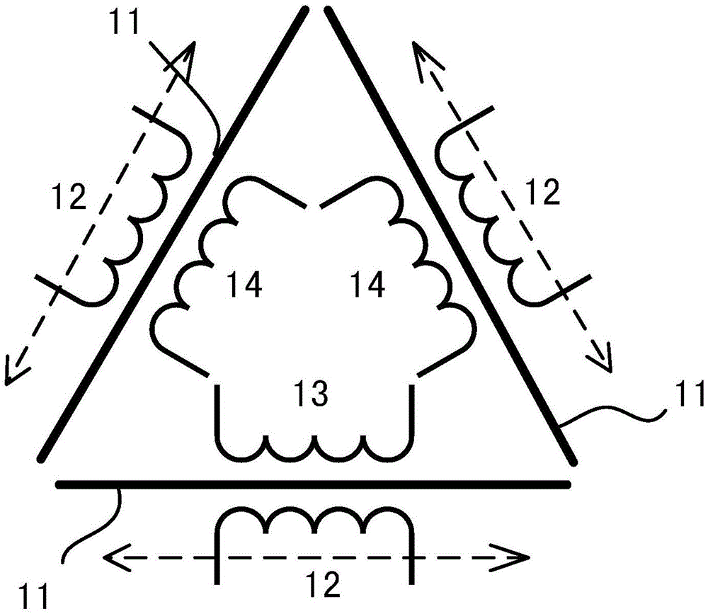
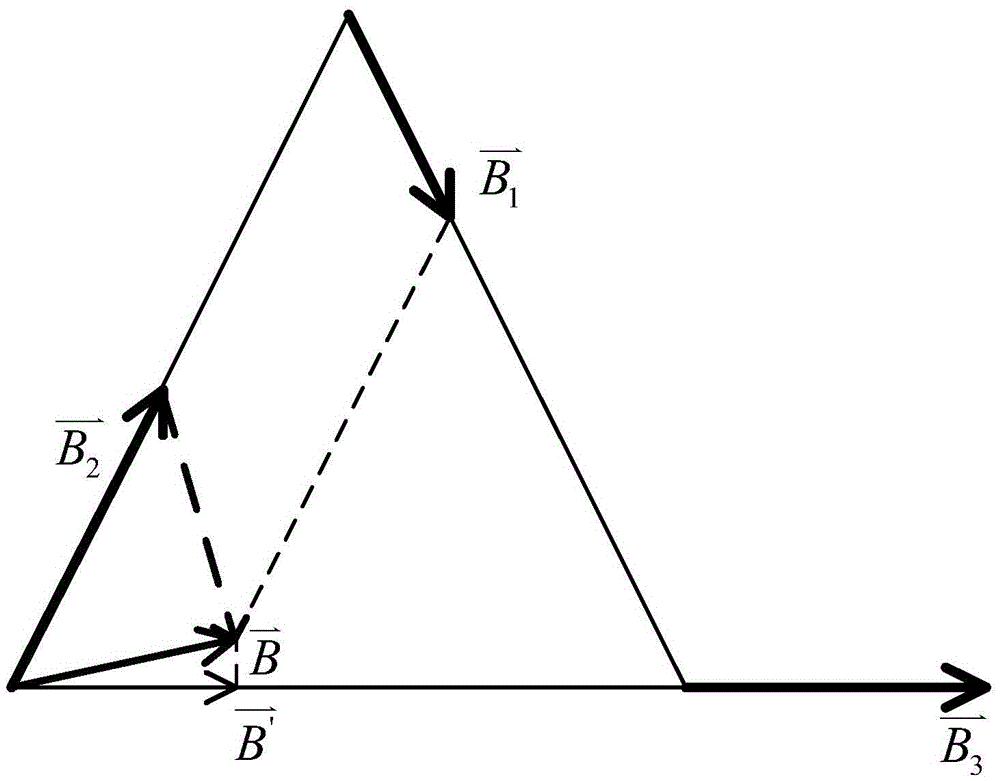
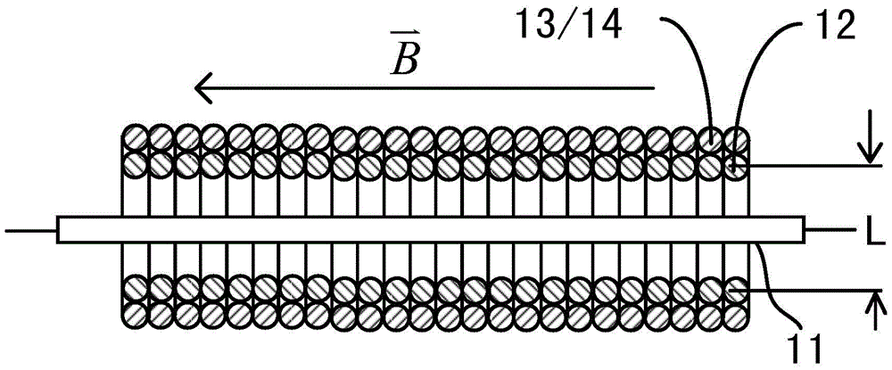
[0030] like figure 1As shown, the magnetic brain signal probe based on the GMI effect of this embodiment includes at least three groups of amorphous wires 11 arranged on the same plane and in the shape of straight strips, and each group of amorphous wires 11 includes one amorphous wire 11 , an angle is formed between any adjacent two groups of amorphous wires 11, each group of amorphous wires 11 is covered with a pick-up coil 12, and each group of amorphous wires 11 can also be two or more as required The amorphous wire 11 . This embodiment includes at least three groups of amorphous wires 11 arranged on the same plane and in a straight strip shape. An angle is formed between any adjacent two groups of amorphous wires 11. If the measurement of the planar magnetic field is performed, only the The distribution of the spatial magnetic field on the plane can be obtained by two measurements, including not only the magnitude of the magnetic field, but also the direction of the magn...
Embodiment 2
[0045] like Image 6 As shown, this embodiment is basically the same as Embodiment 1, and the main differences are: in Embodiment 1, a set of amorphous wires 11 is provided with a feedback coil 13, and two groups of amorphous wires 11 are provided with a correction coil. zero coil 14, so the initialization Figure 4 When the circuit shown is connected, one of the two zero calibration coils 14 can be selected arbitrarily as required. And in the present embodiment, two groups of amorphous wires 11 are provided with feedback coils 13, and one group of amorphous wires 11 is provided with zero calibration coils 14, so in the initialization Figure 4 When the circuit shown is connected, one of the two feedback coils 13 can be arbitrarily selected according to needs, and its working principle is exactly the same as that of the first embodiment, so it will not be repeated here.
PUM
 Abstract
Description
Claims
Application Information
 - R&D
- Intellectual Property
- Life Sciences
- Materials
- Tech Scout
- Unparalleled Data Quality
- Higher Quality Content
- 60% Fewer Hallucinations
Browse by: Latest US Patents, China's latest patents, Technical Efficacy Thesaurus, Application Domain, Technology Topic, Popular Technical Reports.
© 2025 PatSnap. All rights reserved.Legal|Privacy policy|Modern Slavery Act Transparency Statement|Sitemap|About US| Contact US: help@patsnap.com


