
Sheet cropping equipment

A cutting and equipment technology, used in metal processing equipment, feeding devices, positioning devices, etc., can solve the problems of labor and man-hours, low production efficiency, poor products, etc., to avoid manufacturing, facilitate the replacement of equipment, save money The effect of production costs

Inactive Publication Date: 2016-04-06
昆山金群力精密组件有限公司
View PDF0 Cites 4 Cited by
  • Summary
  • Abstract
  • Description
  • Claims
  • Application Information

AI Technical Summary

Problems solved by technology

[0002] Metal parts are indispensable in the electronics industry. Metal parts are stamped by continuous metal molds. A reel of material tape is stored one by one. Before assembly, the entire reel of material tape needs to be cut into small pieces of specified length. , the current cutting equipment has simple functions and cannot be automatically adjusted during the tape pulling process. For products with no shape, especially elastic bending structures, the product is often deformed due to the excessive tension of the paper tape when the paper tray is collected. Subsequent assembly brings problems, and it is easy to cause defective products after assembly. Currently, segmental cutting and product blanking are all operated by special equipment. The factory needs to prepare various cutting and blanking equipment, resulting in high production costs. Not too small, it still takes up space, and when used, it needs to be assembled separately, which consumes manpower and man-hours, resulting in low production efficiency

Method used


Image

  • Sheet cropping equipment
  • Sheet cropping equipment
  • Sheet cropping equipment

Examples


Embodiment

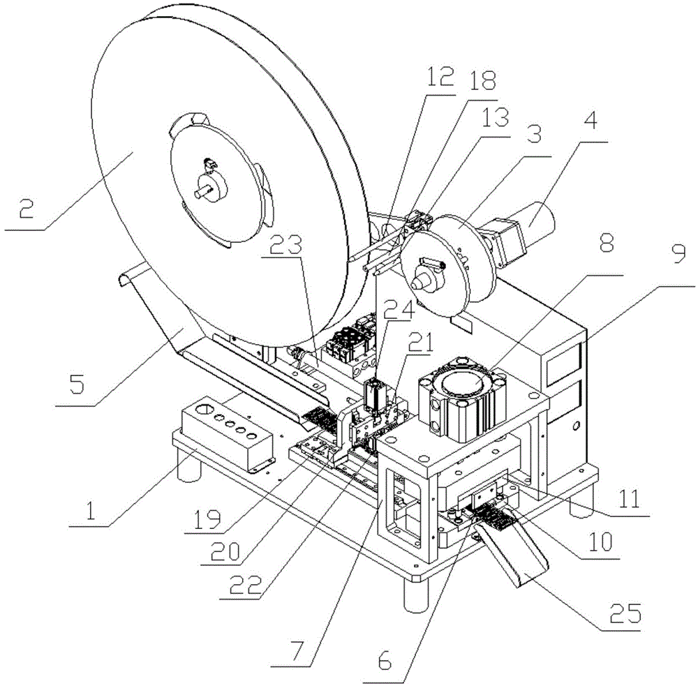
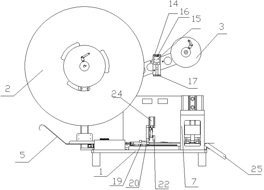
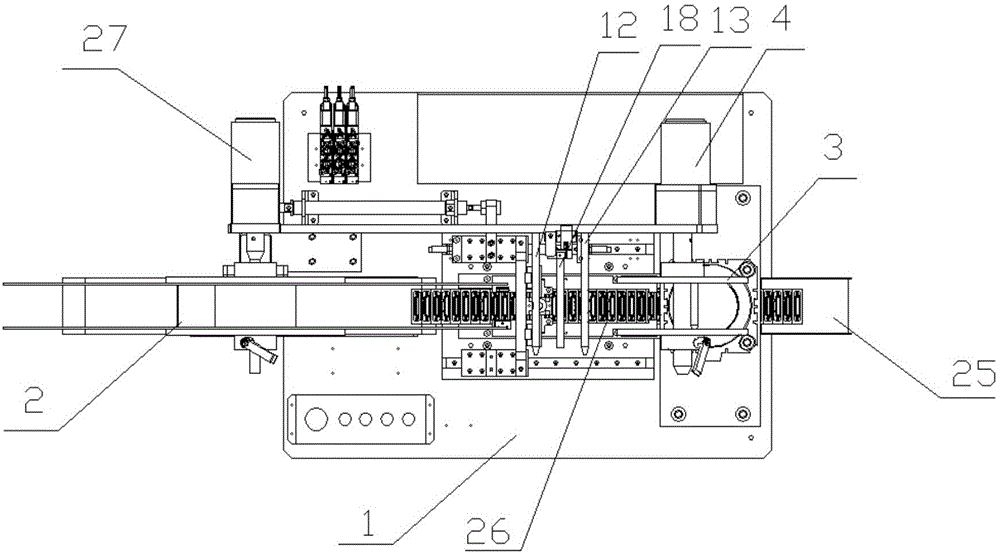
[0017] Embodiment: A kind of sheet material cutting equipment, comprises workbench 1, material tray 2, material tray support 20, paper tray 3, paper tape tension state sensing device, paper tray driving device 4, material tray driving device 27, material Belt track 5, material belt conveying channel 6, material pulling device, stamping die 7, material pulling driving device, punching driving device 8 and controller 9, the material tray bracket 20 is fixedly installed above one end of the workbench 1, and the material tray 2 and the paper tray 3 can be rotated and positioned on the tray support 20 respectively, the tray driving device 27 drives the tray 2 to rotate, the tray 2 is wound with a material tape wrapped with paper tape, and the tray driving device 4 drives the tray 3 to rotate , the paper tape tension state sensing device can sense the tension of the material tape pulled out from the material tray 2 into the paper tray 3 and send a letter to the controller 9. The mate...


PUM


Abstract

The invention discloses sheet cropping equipment. A material plate is driven by a material plate driving device to rotate. A paper plate is driven by a paper plate driving device to rotate. A paper tape tensioning state inducing device can induce the tension condition of a material strap which is drawn out of the material plate to enter the paper plate and transmit information to a controller. A material strap track is exactly located right below the material plate and connected with a material conveying channel. The material plate, a material plate support, the material strap and the material strap track can form a conduction loop to be electrically connected with the controller. The material plate support is connected with a lower-voltage power source. A material pulling device is fixed over the material conveying channel. A material pulling driving device can drive the material pulling device to pull the material strap to move. A material strap channel exactly passes through a knife edge of a lower die body of a stamping die. A plunger chip is arranged on an upper die body. The upper die body is driven by a stamping driving device to move longitudinally. The controller controls actions of all devices. According to the sheet cropping equipment, multiple functions are achieved through the equipment; the production cost is reduced; the production efficiency is improved; deformation of products is avoided due to the fact that the products are not tensioned by a paper tape, and the defective rate of the products is decreased.

Description

technical field [0001] The invention relates to an automatic device, in particular to a sheet material cutting device. Background technique [0002] Metal parts are indispensable in the electronics industry. Metal parts are stamped by continuous metal molds. A reel of material tape is stored one by one. Before assembly, the entire reel of material tape needs to be cut into small pieces of specified length. , the current cutting equipment has simple functions and cannot be automatically adjusted during the tape pulling process. For products with no shape, especially elastic bending structures, the product is often deformed due to the excessive tension of the paper tape when the paper tray is collected. Subsequent assembly brings problems, and it is easy to cause defective products after assembly. Currently, segmental cutting and product blanking are all operated by special equipment. The factory needs to prepare various cutting and blanking equipment, resulting in high produc...

Claims


Application Information

Patent Timeline
IPC IPC(8): B21D28/02B21D28/04B21D28/14B21D43/13B21D45/00B21C51/00
Inventor 蒋仁涛
Owner 昆山金群力精密组件有限公司
Learn More