Oil mist sealing structure of a hydroelectric generator

A hydroelectric generator and sealing structure technology, which is applied to engine sealing, engine components, mechanical equipment, etc., can solve problems such as poor wear resistance, complex structure, and poor insulation

Active Publication Date: 2018-03-16
ZIGONG ZHAOQIANG ENVIRONMENTAL PROTECTION TECH
View PDF7 Cites 0 Cited by
  • Summary
  • Abstract
  • Description
  • Claims
  • Application Information

AI Technical Summary

Problems solved by technology

Felt seals have poor self-lubricating properties and poor wear resistance, which fundamentally cannot solve the escape of oil mist
Spring-supported slider mechanical seals are similar to felt seals, but have poor insulation, complex structures, need to consume air sources, and are expensive

Method used


Image

  • Oil mist sealing structure of a hydroelectric generator
  • Oil mist sealing structure of a hydroelectric generator
  • Oil mist sealing structure of a hydroelectric generator

Examples


Embodiment Construction

[0021] Below in conjunction with accompanying drawing, the present invention is described in detail.

[0022] In order to make the object, technical solution and advantages of the present invention clearer, the present invention will be further described in detail below in conjunction with the accompanying drawings and embodiments. It should be understood that the specific embodiments described here are only used to explain the present invention, not to limit the present invention.

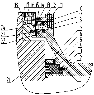
[0023] Such as Figure 1-4 Shown is an embodiment of an oil mist sealing structure of a hydraulic generator according to the present invention. An oil mist sealing structure of a hydraulic generator includes: a main shaft sleeve 21, and a bearing sealing cover 1 is arranged on the outside of the main shaft sleeve 21, and the bearing There are two annular grooves on the sealing cover 1, including an upper groove and a lower groove. A magnetic liquid sealing device is arranged in the upper groove, ...


PUM


Abstract

The invention discloses an oil mist sealing structure of a hydraulic generator and belongs to the field of power generation equipment. The oil mist sealing structure is composed of a zero-clearance sealing part and a magnetic liquid sealing part, achieves rotary combined seal and is applicable to bearing oil mist seal of the hydraulic generator from the low speed to the high speed. A sealing shell of a combined sealing device is formed by connecting four bearing sealing covers through bolts. Firstly, four sealing split bodies are installed on the lower portions of the bearing sealing covers, composite flexible materials are adopted in the circumferential direction to connect the four sealing split bodies, zero-clearance sealing is formed under the radial and axial thrust effect of a small spring, and bearing oil mist is well sealed; then, by means of the magnetic liquid seal on the upper portions of the bearing sealing covers, the zero-leakage sealing effect is achieved; by combining the two kinds of seal, air pressure of a sealing cavity formed by the upper seal and the lower seal can be effectively kept, no negative pressure is produced in the cavity, overflow caused by the pressure difference between the high internal pressure and low bearing sealing cover external pressure can be effectively prevented, and the service life of the oil mist seal is prolonged.

Description

technical field [0001] The invention belongs to the field of power generation equipment, and in particular relates to an oil mist sealing structure of a water turbine generator. Background technique [0002] Judging from the information fed back from the guide bearings and thrust bearings of the vertical turbine generators in the hydropower station, oil throwing and oil mist overflow are the biggest problems. Long-term oil mist overflow will cause: (1) Oil mist and dust will be adsorbed on the stator for a long time Corrosion on the insulation layer of the rotor and the rotor, resulting in a decrease in insulation performance, causing short circuit or breakdown of the stator and rotor coils of the generator, threatening the safety of the generator; (2) oil mist and dust in the stator core ventilation ditch and rotor magnetic pole ventilation ditch Accumulated at places, resulting in poor ventilation and heat dissipation of the generator, seriously affecting the heat dissipat...

Claims


Application Information

Patent Timeline
Patent Type & Authority Patents(China)
IPC IPC(8): F16J15/53F16J15/43
CPCF16J15/43
Inventor 罗小松颜招强晏松坚
Owner ZIGONG ZHAOQIANG ENVIRONMENTAL PROTECTION TECH
Why Eureka
Try Eureka