[0045] The specific embodiments of the present invention will be described below in conjunction with the technical solution and the drawings.
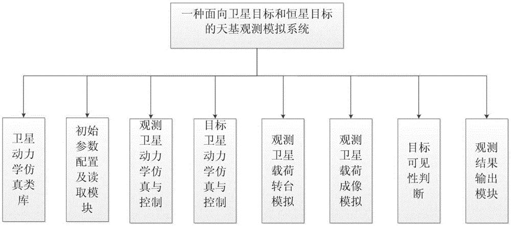
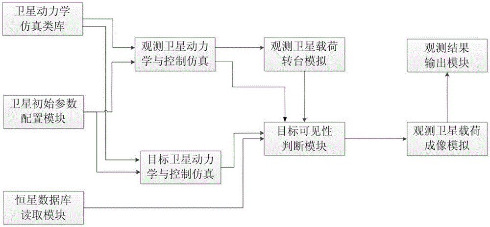
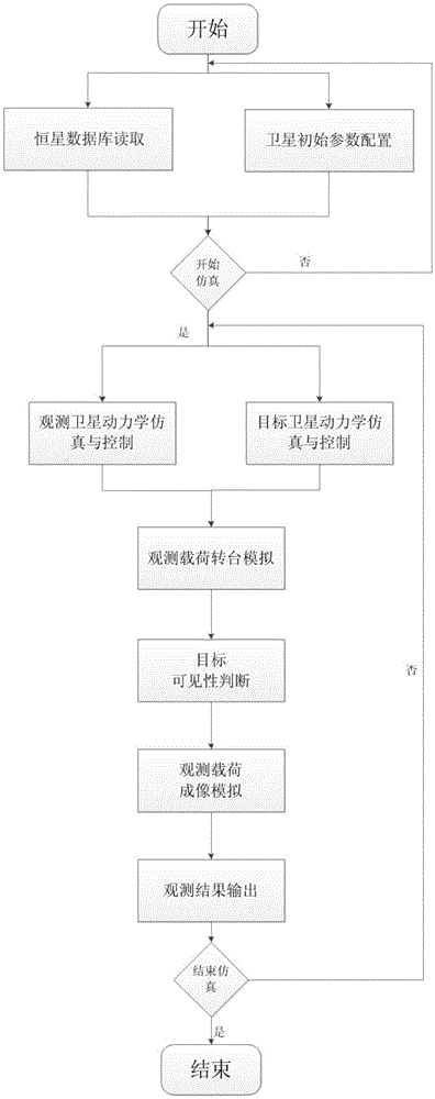
[0046] Such as figure 1 , 2 As shown, the present invention provides a space-based observation simulation system for satellite targets and stellar targets. It mainly includes the stellar database reading module, satellite dynamics simulation class library, satellite initial parameter configuration module, observation satellite dynamics simulation and control, target satellite dynamics simulation and control, observation satellite load turntable simulation module, target visibility judgment module, Observation satellite payload imaging simulation, observation result simulation output module, the data communication between each module is mainly realized through the form of internal interface, the operation process of the whole system is as follows image 3 Shown.
[0047] The data conversion between different coordinate systems is realized through the coordinate conversion matrix. The coordinate system involved in the space-based observation simulation system for satellite targets and stellar targets includes geocentric inertial system, orbital coordinate system, body coordinate system, load turntable coordinate system and image plane coordinate system, which are defined as follows:
[0048] Geocentric inertial system, referred to as i system: O i X i Y i Z i , Where the origin O i Located in the center of the earth, O i X i Point to the vernal equinox, O i Z i Is the rotation axis, pointing to the north pole, O i Y i With O i X i And O i Z i Into the right hand system.
[0049] Orbital coordinate system, o system for short: OX o Y o Z o , Where the origin O is at the center of mass of the satellite, OX o Consistent with the target speed direction, OZ o Point to the center of the earth, OY o With OX o And OZ o Into the right hand system.
[0050] Satellite body coordinate system, referred to as b system: OX b Y b Z b , Where the origin O is at the center of mass of the satellite, OX b , OY b , OZ b The three axes are fixedly connected to the star and are the directions of the three main inertia axes of the satellite, where OX b Is the rolling axis, OY b Is the pitch axis, OZ b Is the yaw axis.
[0051] Load turntable coordinate system, referred to as p system: O p X p Y p Z p , Origin O p At the projection center of the load optical lens, O p Z p Is the direction of the load optical axis, O p X p And O p Y p Parallel to the two sides of the CCD/CMOS, the direction is consistent with the arrangement order of the CCD, which satisfies the right-hand rule.
[0052] Image plane coordinate system, referred to as c system: O c X c Y c Z c , Origin O c Is the origin of the load coordinate system O p Projection on the CCD plane, O c X c And O c Y c And load coordinate system O p X p And O p Y p The direction is the same.
[0053] The geocentric inertial system and orbital coordinate system such as Figure 4 As shown, the load turntable coordinate system and the image plane coordinate system are as Figure 5 Shown.
[0054] The stellar database reading module reads the real star catalog data and converts the longitude and latitude information of the catalog to the position vector information under the geocentric inertial system, records the position vector and magnitude information of each star, and provides the target visibility Judgment module. The stellar database covers databases with different ranges from 5 to 13 magnitudes. Specific information includes right ascension α, declination δ and magnitude level.
[0055] r x =R*cosδ*cosα
[0056] r y =R*cosδ*sinα
[0057] r z =R*sinδ
[0058] Where (r x ,r y ,r z ) Is the position vector of the star’s geocentric inertial system, and R is the set radius of the celestial sphere.
[0059] The satellite dynamics simulation library provides the function of satellite orbit and attitude dynamics simulation with different dynamic precision models and numerical integration methods with different precisions in an object-oriented manner, for the dynamic simulation and control of the observation satellite and the power of the target satellite Learning simulation and control block calls, with high reusability and scalability; different dynamic accuracy models can cover two-body models, J2 perturbation models, etc., which can be customized according to the accuracy model requirements; different numerical integration calculation methods, Including Gill method and 7-order Runge-Kutta method, etc., which can be customized according to the accuracy requirements.
[0060] The satellite orbit model is in the geocentric inertial system, and the position vector of the satellite is The kinematic model is:
[0061] r → ·· = F 0 ( r → ) + F z ( r → , r → · , t ) + F c ( t )
[0062] Among them, r is the position vector of the satellite in the geocentric inertial system, F 0 Is the gravitational acceleration in the center of the earth, F z It is the perturbation acceleration of the satellite by other mechanical factors (that is, the perturbation source) except the gravitational acceleration of the center of the earth, F c In order to control the force acceleration, t is the satellite running time. According to the accuracy of the dynamic model, different perturbation source models are considered, and the custom addition of different types of perturbation sources is supported.
[0063] The attitude kinematics models of the target and platform are described by the four-element method:
[0064] q 1 · q 2 · q 3 · q 4 · = 1 / 2 q 4 - q 3 q 2 q 1 q 3 q 4 - q 1 q 2 - q 2 q 1 q 4 q 3 - q 1 - q 2 - q 3 q 4 ω x - ω o x ω y - ω o y ω z - ω o z 0
[0065] Where (q 1 ,q 2 ,q 3 ,q 4 ) Is the satellite body relative to the four elements under the orbit, (ω x ,ω y ,ω z ) Is the three-axis absolute angular velocity of the satellite in this system, (ω ox ,ω oy ,ω oz ) Is the triaxial component of the orbital angular velocity of the star in this system.
[0066] The satellite attitude kinematics equation is:
[0067]
[0068] Where w s Is the absolute angular velocity of the satellite in this system, I s Is the total star moment of inertia of the satellite relative to the center of mass system of the star, H w Is the moment of inertia of the flywheel, and T is the total external moment of the satellite.
[0069] Satellite initial parameter configuration module, the simulation time setting, the initial motion state and physical parameter configuration of the observation satellite and payload, the initial motion state and physical parameter configuration of the target satellite, the orbit control configuration of the observation satellite and the target satellite, the observation satellite and the target The satellite's attitude control mode configuration is used as the initial simulation parameter for the dynamic simulation and control module of the observation satellite and the dynamic simulation and control module of the target satellite. The initial state of motion includes the satellite's orbits a, e, i, ω, Ω, f, which are the satellite's semi-major axis, eccentricity, orbit inclination, argument of perigee, right ascension of the ascending node, true perigee angle, and initial attitude θ,φ, They are roll angle, pitch angle, yaw angle, roll speed, pitch angle speed and yaw angle speed. The physical parameters include the moment of inertia I of the satellite and the initial installation matrix of the observation satellite load Load focal length f, load field of view type, load field of view size Inch, imaging CCD size CCD_x, CCD_y, orbit control mode configuration includes configuration of orbit control time and pulse increment, attitude control mode configuration includes different mission stages of satellites The status word of the attitude control mode.
[0070] Observation satellite dynamics simulation and control module. At the beginning of the simulation, according to the initial data of the observation satellite provided by the initial parameter configuration module, the observation satellite orbit and attitude dynamics simulation and control system simulation are carried out; when the observation satellite dynamics simulation, according to the dynamics Model accuracy requires calling different dynamic models and numerical integration methods in the satellite dynamics simulation library; when the observation satellite control system is simulated, the pulse orbit change control at the set time is performed according to the preset satellite orbit control configuration parameters; according to the observation satellite Attitude control mode configuration parameters, apply PID control law method, carry out the design of attitude control system in different attitude control modes, and output the three-axis position vector and attitude in the geocentric inertial system of the observation satellite to the target when a control loop is completed The visibility judgment module also outputs the conversion matrix C of the observation satellite orbit system relative to the geocentric inertial system oi , The conversion matrix C of this system relative to the orbital system bo Give the observation satellite load turntable simulation module. The whole calculation process is as Image 6 Shown.
[0071] The calculation formula of the conversion matrix of the orbit system relative to the geocentric inertial system is:
[0072] c o i = 0 1 0 0 0 - 1 - 1 0 0 c o s ( ω + f ) s i n ( ω + f ) 0 - s i n ( ω + f ) cos ( ω + f ) 0 0 0 1 1 0 0 0 cos i sin i 0 - sin i cos i c o s Ω s i n Ω 0 - s i n Ω c o s Ω 0 0 0 1
[0073] The conversion matrix of the satellite system relative to the orbit system is:
[0074] C b o = q 1 2 - q 2 2 - q 3 2 + q 4 2 2 ( q 1 q 2 + q 3 q 4 ) 2 ( q 1 q 3 - q 2 q 4 ) 2 ( q 1 q 2 - q 3 q 4 ) - q 1 2 + q 2 2 - q 3 2 + q 4 2 2 ( q 1 q 4 + q 2 q 3 ) 2 ( q 1 q 3 + q 2 q 4 ) 2 ( - q 1 q 4 + q 2 q 3 ) - q 1 2 - q 2 2 + q 3 2 + q 4 2
[0075] The calculation formula of the control torque under the PID control law based on feedback four elements is:
[0076] T cx =2*K xp *q 1E *q 4E +K xd *w x
[0077] T cy =2*K yp *q 1E *q 4E +K yd *w y
[0078] T cz =2*K zp *q 1E *q 4E +K zd *w z
[0079] Where q e =(q 1E ,q 2E ,q 3E ,q 4E ) Is the four elements of error, (T cx ,T cy ,T cz ) Is the three-axis control torque under the satellite system, (K xp ,K xd ) Is the PD control parameter of the x-axis in the satellite system, (K yp ,K yd ) Is the PD control parameter of the y-axis under the satellite system, (K zp ,K zd ) Is the PD control parameter of the z-axis in the satellite system.
[0080] Target satellite dynamics simulation and control module. At the beginning of the simulation, according to the initial data of the target satellite provided by the initial parameter configuration of the target satellite, the target satellite's orbit and attitude dynamics and control system simulation are carried out; when the target satellite dynamics is simulated, it is based on the dynamic model The accuracy requirements call different dynamic models and numerical integration methods in the satellite dynamics simulation class library; when the target satellite control system is simulated, the pulse orbit change control at the set time is performed according to the preset target satellite orbit control configuration parameters, and according to the target satellite Attitude control mode configuration parameters, apply PID control law control method, carry out the design of attitude control systems in different attitude control modes, and output the three-axis position vector and attitude feedback of the target satellite under the geocentric inertial system when a control loop is completed Target visibility judgment module. The whole calculation process is as Image 6 Shown.
[0081] The observation satellite load turntable simulation is responsible for simulating the pitch and yaw movement of the load turntable on the satellite platform. The pitch movement is realized by the y-axis rotation of the load turntable, and the yaw movement is realized by the x-axis rotation of the load turntable. There are two load turntable motion modes: the sky survey mode and the target tracking mode. The sky survey mode is responsible for the initial stage of target search and detection, and the target tracking mode is responsible for target identification and tracking. The module outputs the pitch angle θ'and yaw angle φ'of the turntable at each simulation moment, and the conversion matrix of the actual position of the turntable relative to its initial installation position The formula for calculating the conversion matrix by pitch angle and yaw angle is as follows.
[0082] C p r e p i n = cosθ , 0 sinθ , 0 1 0 - sinθ , 0 cosθ , 1 0 0 0 cosφ , sinφ , 0 - sinφ , cosφ ,
[0083] The target visibility judgment module includes the visibility judgment of the star target and the visibility judgment of the satellite target. During the simulation process, the receiving star database reads the position vector and magnitude of the star in the geocentric inertial system from the module, and receives the three-axis position vector sum of the target in the geocentric inertial system from the target satellite dynamics simulation and control module. Attitude, receive the three-axis position vector and attitude of the observation satellite from the observation satellite dynamics simulation and control module, and receive the conversion matrix of the payload turntable relative to the geocentric inertial system from the observation satellite load turntable simulation module, in each simulation Calculate the relationship between the angle between the relative position vector of the target to the observation satellite and the load optical axis vector of the observation satellite and the field of view at all times to meet the conditions that the earth is not blocked, the sun and the moon are not in the field of view, and the target is in the field of view. Record this The relative position of the target. For satellite targets, the equivalent magnitude is calculated according to the relative position. For stellar targets, the magnitude value is directly recorded, and the recording results and the conversion matrix of the load relative to the geocentric inertial system are provided to the observation satellite load imaging Analog module
[0084] When the earth is occluded, the target enters the shadow of the earth and cannot be illuminated by the sun, and the detection system cannot observe the target; sunlight influence means that the angle between the vector of the target relative to the observation satellite and the vector of the sun relative to the observation satellite is greater than a certain critical angle. The angle is the sum of the apparent radius of the sun and the light scattering angle. The effect of moonlight is the same as that of sunlight. The field of view condition is to judge whether the angle formed by the position vector of the target relative to the observation load and the optical axis of the load is less than the critical value of the field of view. If it is less, the imaging condition is satisfied. χ represents the angle between the target position vector and the load optical axis in the observation load coordinate system. The calculation formula is:
[0085] χ = arccos ( r p → · r l → )
[0086] r p → = x p y p z p Represents the target position vector in the observation load coordinate system, r l → = 0 0 z l Represents the optical axis position vector in the observed load coordinate system.
[0087] The inequality condition for judging whether it is in the field of view is:
[0088] χ≤AngView
[0089] Where AngView is the critical angle of the load field of view. If the inequality condition is satisfied, the observation target is in the load field of view, otherwise it is not in the field of view.
[0090] Observation satellite payload imaging simulation module, receiving the visible target information transmitted by the target visibility judgment module, the conversion matrix of the payload relative to the geocentric inertial system, based on the position vector of the visible target in the imaging coordinate system, the imaging coordinate system and the load image plane coordinates System relationship, two-dimensional projection of the target position in the image plane coordinate system, and calculate and output its position in the image plane coordinate system at each simulation time, for the observation result output module to call, and save it in the form of a text file Space-based observation results at each simulation time.
[0091] The main calculation contents include:
[0092] ●Calculate the position vector of the target in the observation load coordinate system:
[0093] x p y p z p = C p r e p i n C p i n b C b o C o i ( x i t y i t z i t - x i c y i c z i c )
[0094] among them, x i t y i t z i t Represents the position vector of the target in the geocentric inertial system, x i c y i c z i c Represents the position vector of the observation satellite in the geocentric inertial system, Represents the conversion matrix of the observation satellite load turntable relative to the geocentric inertial system, x p y p z p Represents the target position vector in the observed load coordinate system.
[0095] ●The position of the calculation target in the image plane coordinate system is:
[0096] x = x p z p * f
[0097] y = y p z p * f
[0098] Where f is the focal length of the observation load, and (x, y) represents the coordinate value of the target in the image plane coordinate system.
[0099] Observation result output module, based on the position of the visible target in the image plane coordinate system and the target magnitude information transmitted by the observation satellite payload imaging simulation module, using computer rendering technology to draw the payload imaging window and the visible target in the window to complete the alignment The simulation output of the space-based observation results, and save the space-based observation results at each simulation time in the form of picture format. The space-based observation simulation results of long-distance observation are as Image 6 As shown, the space-based observation simulation results of close observation are as Figure 7 Shown.
[0100] In short, the present invention uses computer simulation technology to construct a space-based observation simulation system for satellite targets and stellar targets for the observation satellite, the actual operating state of the satellite target, the actual physical state of the observation load installed by the observation satellite, and the information of the stellar target. , Realizes the simulation simulation of the space-based observation system, and outputs the observation simulation results at each simulation time in the form of data and images. Taking the entire space-based observation physical process simulation as the starting point, construct and simulate the space-based observation process including observation satellites, observation payloads, target satellites, stars, etc., and dynamically output the space-based observation simulation results with high confidence.