Method of utilizing binary zone plate to design diffraction multi-focus element and realize axial direction multi-focus optical path structure

A multi-focus, zone plate technology, used in optical components, optics, instruments, etc., can solve the problem of inability to accurately control the uniformity and quantity of focal energy

Pending Publication Date: 2016-04-06
北京润和微光科技有限公司
View PDF4 Cites 8 Cited by
  • Summary
  • Abstract
  • Description
  • Claims
  • Application Information

AI Technical Summary

Problems solved by technology

Binary Fresnel zone plates can also achieve multi-focus, but this method cannot accurately control the uniformity and quantity of focus energy

Method used


Image

  • Method of utilizing binary zone plate to design diffraction multi-focus element and realize axial direction multi-focus optical path structure
  • Method of utilizing binary zone plate to design diffraction multi-focus element and realize axial direction multi-focus optical path structure
  • Method of utilizing binary zone plate to design diffraction multi-focus element and realize axial direction multi-focus optical path structure

Examples


example 1

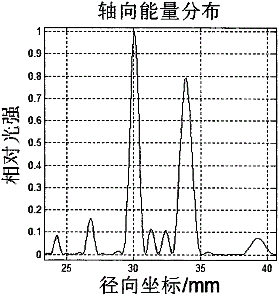
[0022] Example 1 achieves a uniform bifocal element design.

[0023] Incident laser wavelength λ=1.064μm, spot radius R=1.5mm The focal length of the first focal point is f a =30mm, the focal length of the second focal point is f b = 34mm.

[0024] Step 1: Obtain the focal length f of the diffraction element from the focal length of the target focal point 1 , and the focal length of the focusing mirror f 2 .

[0025] The second step: expand and collimate the laser beam to meet the requirements of the diffractive multi-focus element for incident light.

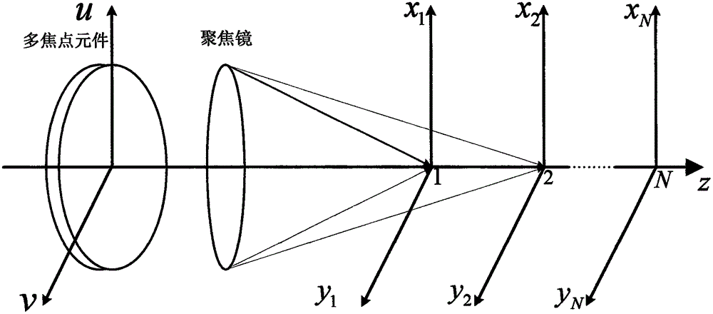
[0026] Step 3: Build the optical path according to the design plan. In the optical path, there are diffractive multi-focus elements and focusing mirrors in sequence along the laser emission direction.

[0027] Step 4: Adjust the position of the image plane along the optical axis, and observe the spot distribution in turn.

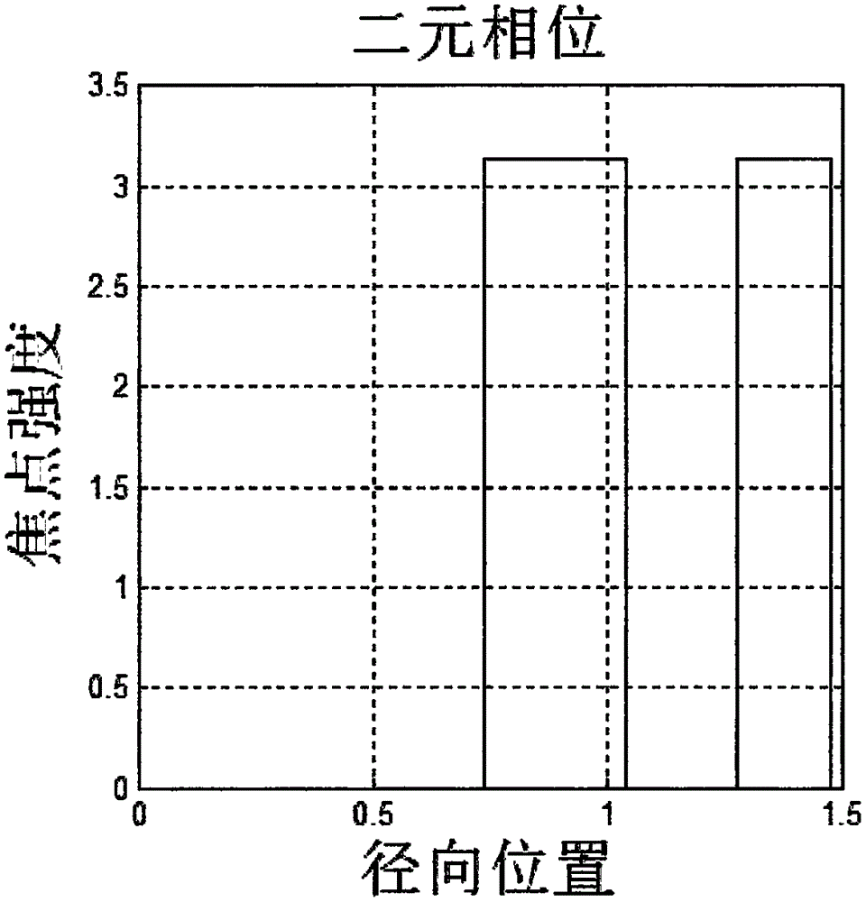
[0028] The designed radial binary phase distribution of the multi-focus element is as follows: fi...


PUM


Abstract

The invention provides a method of utilizing a binary zone plate to design a diffraction multi-focus element, and realize an axial direction multi-focus optical path structure. The optical path structure successively comprises a diffraction multi-focus element, a focusing mirror or a lens module capable of realizing a focusing function along a laser propagation direction. A diffraction multi-focus element and a focusing mirror of corresponding specifications are designed according to laser light source parameters and objective focus parameters. The design method possesses the advantages of high efficiency, simple structure, high luminous energy utilization rate, and flexible focus quantity and energy distribution design.

Description

technical field [0001] The invention proposes a method for designing a diffractive multi-focus element by using a binary zone plate, and realizes an axial multi-focus optical path structure. Background technique [0002] Multifocal elements play a unique role in accommodating intraocular lenses, laser disc pickup heads, and 3-D image construction. [0003] In the laser processing industry, especially the laser cutting industry, higher and higher requirements are put forward for the beam quality. In addition to requiring a more refined spot, there are also requirements for a variety of spot shapes. Among them, multi-focus has been more and more used in fields such as cutting transparent materials (such as glass and sapphire). [0004] There are many ways to generate multiple focal points, and a typical segmented lens is used to achieve multi-focus. Due to the different apertures of different regions, the fields of view of different focal points are different. Binary Fresnel...

Claims


Application Information

Patent Timeline
IPC IPC(8): G02B27/09G02B27/00
CPCG02B27/0012G02B27/0927G02B27/0944
Inventor 刘贺彭亦超王晓峰潘岭峰马衍强
Owner 北京润和微光科技有限公司
Why Eureka
Try Eureka