Safety apparatus for thermal battery soaked in high-temperature alkali liquor for discharging

A technology of safety device and high-temperature lye, which is applied to the parts of primary batteries, battery cover/end cover, battery pack parts, etc., can solve the limitation of the use environment and application range of hot batteries, and cannot meet the requirements and constraints of discharge. Heat battery and other issues, to achieve the effect of ensuring strength and operability, simple structure, and easy processing

Active Publication Date: 2016-04-06
CHINA ELECTRONIC TECH GRP CORP NO 18 RES INST
View PDF4 Cites 1 Cited by
  • Summary
  • Abstract
  • Description
  • Claims
  • Application Information

AI Technical Summary

Problems solved by technology

[0003] At present, the discharge environment of the known thermal battery is in the air. In order to ensure the insulation of the pole, the use environment and application range of the thermal battery are also limited.
With the continuous innovation, development and maturity of thermal batteries, a single discharge environment has become a technical bottleneck restricting the industrial application of thermal batteries in my country, and cannot meet the requirements of discharge in a liquid environment

Method used


Image

  • Safety apparatus for thermal battery soaked in high-temperature alkali liquor for discharging
  • Safety apparatus for thermal battery soaked in high-temperature alkali liquor for discharging
  • Safety apparatus for thermal battery soaked in high-temperature alkali liquor for discharging

Examples


Embodiment Construction

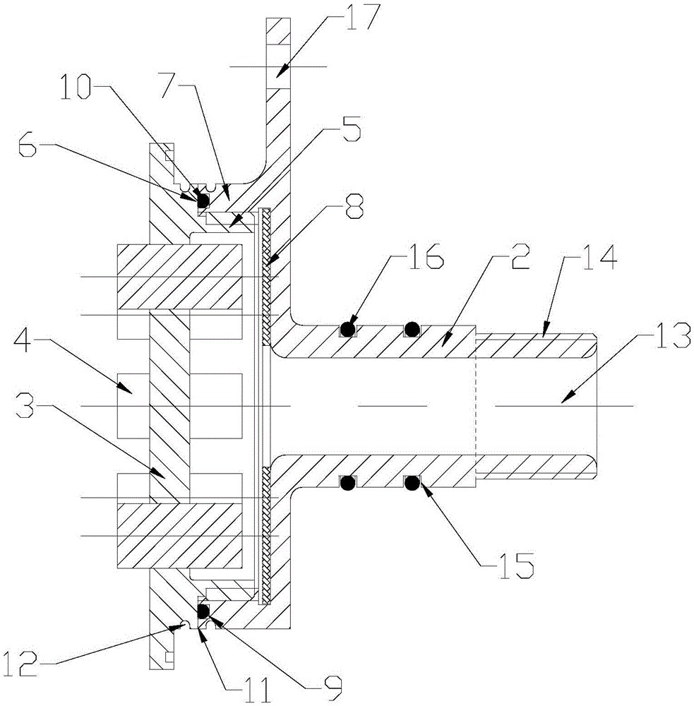
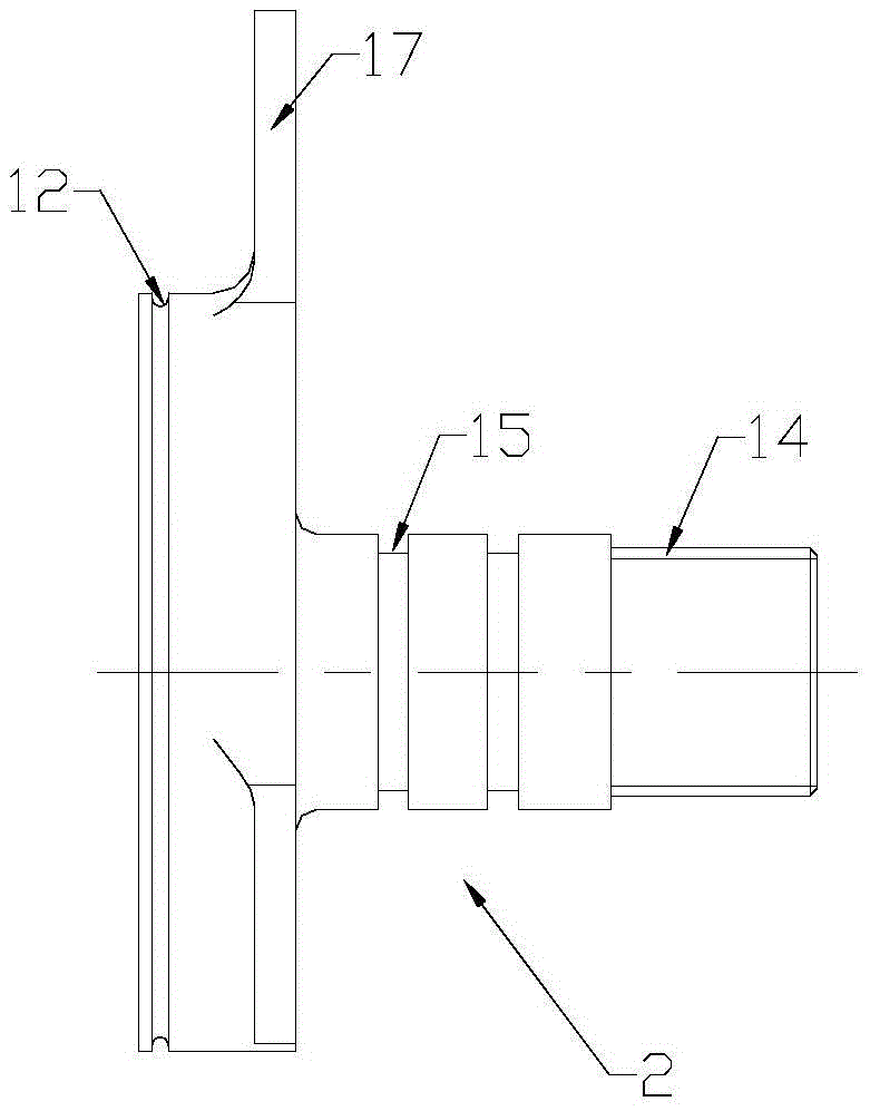
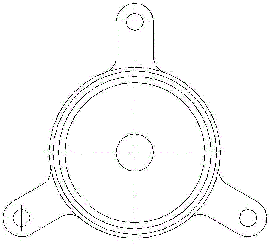
[0027] In order to further understand the invention content, characteristics and effects of the present invention, the following examples are given, and detailed descriptions are as follows in conjunction with the accompanying drawings:

[0028] see Figure 1~5 , a safety device for discharging thermal batteries soaked in high-temperature alkaline solution, including a thermal battery cover 1 and a safety cap 2; the thermal battery cover 1 includes a battery cover body 3 with eight pole holes inside and a battery cover body 3 sealed and fixed in eight pole holes. The thermal battery pole 4 on the pole hole, the battery cover body 3 protrudes an external thread step 5 on the periphery of the thermal battery pole 4, and the outer raised edge 6 between the external thread step 5 and the battery cover body 3; safety The side wall of the cavity at 7 places on the outer edge of the protective cap is provided with an internal thread that matches the external thread of the battery cov...


PUM


Abstract

The invention relates to a safety apparatus for a thermal battery soaked in high-temperature alkali liquor for discharging. The safety apparatus comprises a thermal battery cover and a safety protective cap, wherein the thermal battery cover comprises a battery cover body and a thermal battery terminal post; the battery cover body protrudes in the periphery of the thermal battery terminal post to form an external screw thread stage; an upper protruding-edge protrudes to the outer side between the external screw thread stage and the battery cover body; an internal screw thread matched with the external screw thread of the battery cover body is formed in the inner cavity side in the outer edge of the safety protective cap; an insulating sheet is adhered to the inner cavity in the outer edge of the safety protective cap; a sealing groove is formed in the outer edge of the safety protective cap; a sealing rubber ring is placed in the sealing groove; a welding surface is formed in the junction between the outer edge of the safety protective cap and the upper protruding-edge of the battery cover body; thermal conductive grooves are formed in the battery cover body and the safety protective cap on the left and right sides of the welding surface; a groove is formed in the outer diameter of an outgoing line port of the safety protective cap; the thermal battery leads a connecting wire from the outgoing line port, and the outgoing line port is encapsulated with resin adhesive; the connecting wire is sealed and fixed through the resin adhesive; and an integrally-formed fixed part is arranged on the protective cap.

Description

technical field [0001] The invention belongs to the technical field of thermal batteries, in particular to a safety device for discharging thermal batteries soaked in high-temperature alkaline solution. Background technique [0002] Thermal battery (thermal battery) is also called heat activated reserve battery (heat activated reserve battery). The electrolyte is a non-conductive solid during storage. When in use, an electric ignition head or a firing pin mechanism is used to ignite the heating agent inside, so that the electrolyte melts into an ion conductor and is activated. A reserve battery. It is safe and convenient to use, has strong environmental adaptability, and is an ideal power supply for quick-start devices. Because thermal batteries have unique advantages such as high discharge rate, little influence by ambient temperature, and long storage period, they are widely used in various fields. [0003] At present, the discharge environment of the known thermal batte...

Claims


Application Information

Patent Timeline
IPC IPC(8): H01M6/36H01M6/02H01M2/34H01M2/04H01M50/147H01M50/188H01M50/567H01M50/591
CPCH01M6/02H01M6/36H01M50/147H01M50/572
Inventor 刘伟吕霖娜牛长冬张卫红高新龙王佩霞
Owner CHINA ELECTRONIC TECH GRP CORP NO 18 RES INST
Why Eureka
Try Eureka