Synchronous rectification circuit, wireless charging system and synchronous rectification method
A synchronous rectification and circuit technology, applied in the electronic field, can solve problems such as burrs, and achieve the effects of saving design costs, reducing harsh requirements, and improving efficiency
- Summary
- Abstract
- Description
- Claims
- Application Information
AI Technical Summary
Problems solved by technology
Method used
Image

Examples
Embodiment Construction
[0048] In order to be able to describe the technical content of the present invention more clearly, further description will be given below in conjunction with specific embodiments.
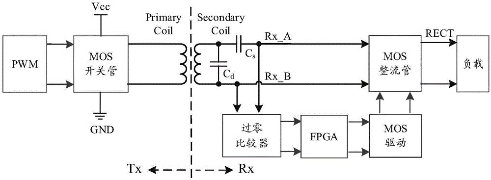
[0049] The purpose of the present invention is to replace the synchronous rectification and self-driving, by collecting the AC signal before rectification and sending it to the hardware circuit for timing processing, eliminating the burr generated when the AC signal is collected, and avoiding the situation that the two inverted output signals of the MOS tube drive are in phase. Improve the safety, reliability and flexibility of synchronous rectification control.
[0050] See figure 1 As shown, the synchronous rectification circuit of the present invention includes:
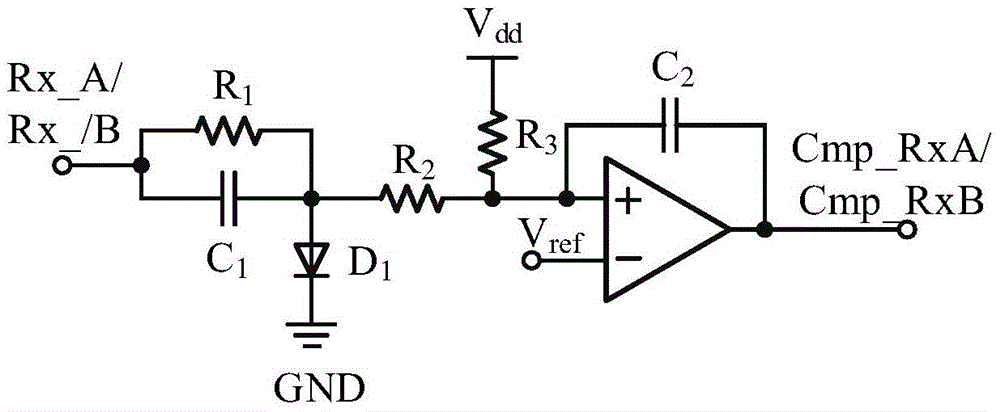
[0051] The zero-crossing comparator is used to process the signal obtained from the coil to obtain the first AC signal and the second AC signal;
[0052] The FPGA module is used to obtain the dead zone protection time according to the signa...
PUM
 Abstract
Description
Claims
Application Information
 - Generate Ideas
- Intellectual Property
- Life Sciences
- Materials
- Tech Scout
- Unparalleled Data Quality
- Higher Quality Content
- 60% Fewer Hallucinations
Browse by: Latest US Patents, China's latest patents, Technical Efficacy Thesaurus, Application Domain, Technology Topic, Popular Technical Reports.
© 2025 PatSnap. All rights reserved.Legal|Privacy policy|Modern Slavery Act Transparency Statement|Sitemap|About US| Contact US: help@patsnap.com