Switch machine notch monitoring system and method based on binocular visual processing identification

A monitoring system and switch machine technology, applied in closed-circuit television systems, measuring devices, instruments, etc., can solve problems such as improving the difficulty and cost of system operation and upgrading, real-time high-definition transmission delay of images and videos, and inability to gap quantitative analysis. , to achieve the effect of enhancing the gold content of technology, reducing the difficulty of development, and reducing the tension of resources

Pending Publication Date: 2016-04-06
JIANGSU GENTURE ELECTRONICS INFORMATION SERVICE CO LTD
View PDF13 Cites 11 Cited by
  • Summary
  • Abstract
  • Description
  • Claims
  • Application Information

AI Technical Summary

Problems solved by technology

The sensor of the direct measurement method is installed in the gap, and its output can directly reflect the size of the measured gap, but the installation is complicated
The indirect measurement method is easy to install, but requires careful adjustment of the reference position
The existing point machine monitoring system has the following problems: First, the electromagnetic measurement used in the existing system is greatly affected by temperature and electromagnetic, and some systems can only qualitatively reflect the state of the gap, and cannot perform quantitative analysis on the gap; Some systems also require different sensors for different switch machines
Second, the existing point machine gap monitoring systems and monitoring principles are diverse, and the various methods are incompatible, which increases the difficulty and cost of system operation and upgrading
Third, most of the existing monitoring systems use ADSL transmission, which brings a large delay to the real-time high-definition transmission of images and videos

Method used


Image

  • Switch machine notch monitoring system and method based on binocular visual processing identification
  • Switch machine notch monitoring system and method based on binocular visual processing identification
  • Switch machine notch monitoring system and method based on binocular visual processing identification

Examples


Embodiment Construction

[0048] The present invention will be described in detail below in conjunction with the accompanying drawings and specific examples.

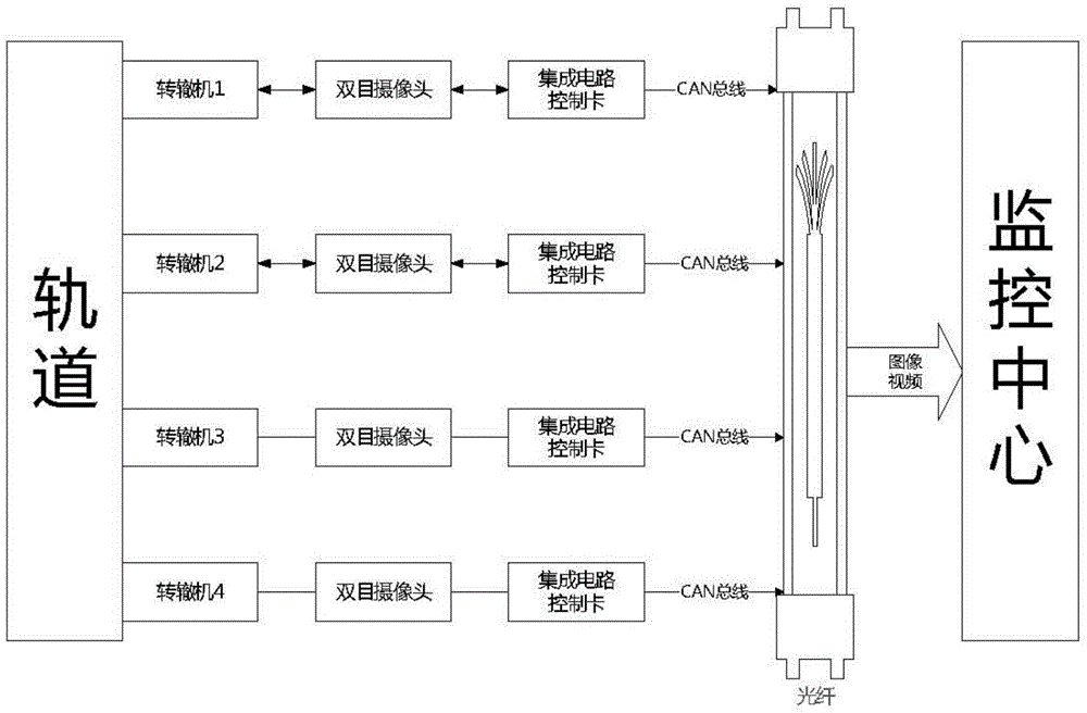
[0049] combine figure 1 As shown, the overall structure of the switch machine gap monitoring system is divided into three major subsystems: the on-site switch machine part, the CAN bus optical fiber transmission part, and the monitoring center part. In the on-site switch machine part, the system needs to install a binocular high-definition camera, aim the lens of the camera at the gap position of the track, and place the two cameras on the left and right symmetrically. The camera is connected to the integrated circuit control card through the USB interface, and the integrated circuit control card Based on the ARM and Linux platforms, the data collected by the camera is encoded, stored, compressed and other operations. In the monitoring center, an image visual processing and recognition system is running. This system processes image and video da...


PUM


Abstract

The invention provides a switch machine notch monitoring system and method based on binocular visual processing identification, relating to the switch machine notch monitoring field. The detection system comprises an on-site binocular collection subsystem, a CAN bus fiber transmission subsystem and a monitoring subsystem. The binocular collection subsystem collects notch images, and transmits the images to the monitoring subsystem through the CAN bus fiber transmission subsystem; the monitoring subsystem performs visual processing, and employs a gauss filter to perform smooth filtering de-noising processing; a Canny edge detector extracts notch edge information, performs Hough transformation on edge images to detect line segments, and identifies line segment information in the images. Through a series of constraint conditions, effective line segments on the top left side of notch edges are screened, reference mark and real marking line segment coordinates are recorded, and notch offsets on the images are calculated according to image geometrical distances. According to proportions, real notch offsets are calculated. A left image and a right image are both processed according to the processing flow, thereby improving calculating accuracy.

Description

technical field [0001] The invention relates to a switch machine gap monitoring system and method, belonging to the field of turnout control in rail transit, in particular to a switch machine gap monitoring system and method based on binocular vision processing recognition. Background technique [0002] The safety and stability monitoring of the switch machine, the actuator of the turnout control system, plays an important role in the safe operation of trains in the rail transit industry. Gap status monitoring data (images and videos) is an important reference for analyzing the operating status of switch machines. [0003] Traditional switch machine gap monitoring methods are divided into two categories: direct measurement and indirect measurement. The sensor of the direct measurement method is installed in the gap, and its output can directly reflect the size of the measured gap, but the installation is complicated. Indirect measurement is easy to install, but requires ca...

Claims


Application Information

Patent Timeline
Patent Type & Authority Applications(China)
IPC IPC(8): H04N7/18G01B11/14B61L23/04
CPCH04N7/18G01B11/14B61L23/04
Inventor 吴旭东杨威沈宇王恺张宽
Owner JIANGSU GENTURE ELECTRONICS INFORMATION SERVICE CO LTD
Why Eureka
Try Eureka