Multi-cutter-location numerical control milling machine

A CNC milling machine, multi-tool technology, applied in the field of mechanical processing, can solve problems such as unreasonable cooling mechanism setting, overheating and scrapping of workpieces, equipment failures, etc., achieve stable and smooth tool changing actions, improve work safety, and prolong service life. Effect

Active Publication Date: 2016-04-13
ZHEJIANG HUAXU IND
View PDF8 Cites 4 Cited by
  • Summary
  • Abstract
  • Description
  • Claims
  • Application Information

AI Technical Summary

Problems solved by technology

The problems existing in the existing technology are: usually only one shape of tool can be clamped for processing at a time, and the tool needs to be replaced manually repeatedly when performing mechanical processing with more complex shapes, which is time-consuming and laborious; multi-tool CNC milling machine with different tools, but the tool change process is complicated, and the tool is exposed relative to the cutter head, which poses safety risks to the equipment itself and the operator; in addition, the existing CNC lathes either have no cooling mechanism or cooling mechanism settings Unreasonable, it is easy to cause the workpiece to be overheated and scrapped; moreover, the existing CNC lathes usually do not deal with cutting chips, and it is easy to cause equipment failure due to cutting chips splashing into the joints of various functional components, which poses a great safety hazard

Method used


Image

  • Multi-cutter-location numerical control milling machine

Examples


Embodiment Construction

[0017] Below in conjunction with specific embodiment and accompanying drawing, the present invention will be further described:

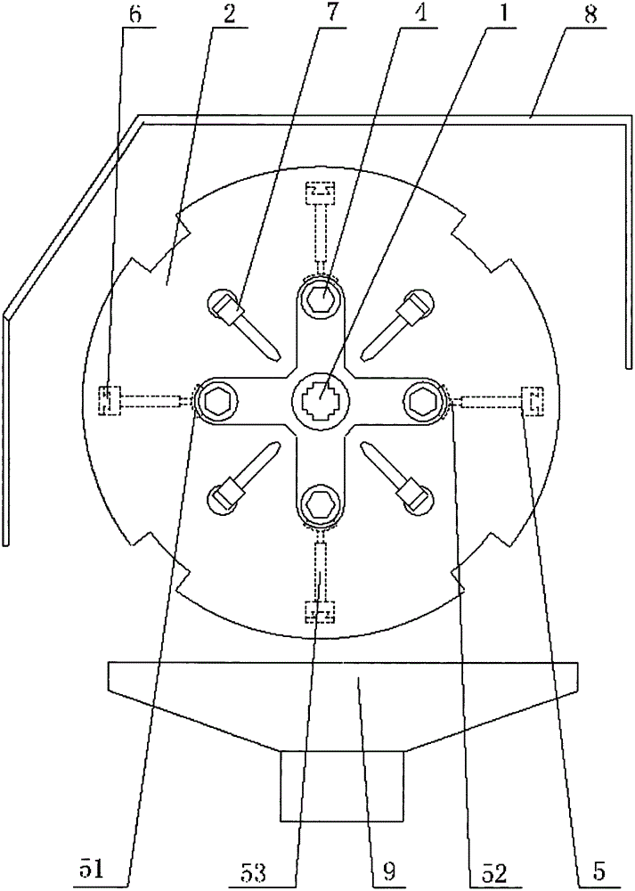
[0018] Refer to attached figure 1 As shown, the multi-cutter CNC milling machine of the present invention includes a workpiece clamping mechanism and a tool clamping mechanism, the workpiece clamping mechanism is provided with a feed drive mechanism, the tool clamping mechanism is provided with a displacement drive mechanism, and the tool clamping mechanism includes a positioning The shaft 1 and the positioning shaft are also equipped with a rotary drive mechanism; the positioning shaft 1 is equipped with a tool disc 2 through a bearing movable sleeve, and the tool disc 2 has at least two tool movable grooves 3, and the tool 4 is arranged on the tool movable slot along the axial direction of the tool disc. In the groove, the tool 2 includes at least two groups of milling cutters with different cutter heads, wherein at least one group of milling cutt...


PUM


Abstract

The invention provides a multi-cutter-location numerical control milling machine which comprises a workpiece clamping mechanism and a cutting tool clamping mechanism. The cutting tool clamping mechanism comprises a positioning shaft, the positioning shaft is provided with a rotation driving mechanism, the positioning shaft is movably sleeved with a cutting tool disc through a bearing, at least two cutting tool moving grooves are formed in the cutting tool disc, a cutter is arranged in each cutter moving groove in a penetrating mode and comprises at least two sets of milling cutters of which cutter heads are in different shapes, and at least one set of the milling cutters are provided with two or more than two cutter heads; a cutter lifting mechanism is arranged in each cutter moving groove and provided with a cutter locking and automatic unlocking mechanism, a cutter resetting mechanism is arranged in each cutter moving groove, and each cutter lifting mechanism is provided with a sliding guide rail mechanism and a lifting sliding drive mechanism; the positioning shaft is provided with a cutter catching mechanism. The multi-cutter-location numerical control milling machine has the advantages that multiple sets of the milling cutters of which the cutter heads are in the different shapes can be used for composite milling, the cutter replacing procedure is optimized, all the sets of the cutting tools are arranged in the cutting tool disc in a hidden mode, and use is safe.

Description

technical field [0001] The invention relates to the field of mechanical processing, in particular to a multi-cutter numerical control milling machine. Background technique [0002] Existing CNC milling machines generally include a workpiece clamping mechanism and a tool clamping mechanism, the workpiece clamping mechanism is provided with a feed drive mechanism, and the tool clamping mechanism is provided with a displacement drive mechanism. The problems existing in the existing technology are: usually only one shape of tool can be clamped at a time for processing, and the tool needs to be replaced manually repeatedly when performing mechanical processing with more complex shapes, which is time-consuming and laborious; multi-tool CNC milling machine with different tools, but the tool change process is complicated, and the tool is exposed relative to the cutter head, which poses safety risks to the equipment itself and the operator; in addition, the existing CNC lathes either...

Claims


Application Information

Patent Timeline
IPC IPC(8): B23C1/04B23C9/00B23Q11/00B23Q11/08
CPCB23C1/04B23C9/00B23Q11/0046B23Q11/08
Inventor 李亦琴
Owner ZHEJIANG HUAXU IND
Why Eureka
Try Eureka