
Liquid fuel vaporization combustion device

A combustion device and technology of liquid fuel, applied in the directions of liquid heating fuel, combustion method, heating fuel, etc., can solve the problems of reduced combustion efficiency, incomplete vaporization, increased air pressure, etc.

Inactive Publication Date: 2016-04-13
XUZHOU LIFANG MECHANICAL & ELECTRICAL EQUIP MFG CO LTD
View PDF13 Cites 1 Cited by
  • Summary
  • Abstract
  • Description
  • Claims
  • Application Information

AI Technical Summary

Problems solved by technology

[0002] Some existing liquid fuel stoves are prone to incomplete combustion, resulting in carbon deposits, odors, black smoke, etc.
Liquid fuel stoves mostly use vaporization devices, some of which use vaporization tubes installed at the bottom of the burner, and use the method of opening holes in the burner to let a part of the vaporization gas spray out to burn and heat the vaporization tube, which will affect the intensity of the main flame and reduce the thermal efficiency; some The vaporization tube is installed horizontally on the top of the burner, causing the main firepower to be split into two halves, reducing the thermal efficiency; Chinese Patent Publication No. CN2079290 discloses a liquid fuel furnace (stove) burner, which discloses a tube type vaporization combustion The device is prone to partial vaporization in the tube, which will cause the local pressure in the vaporization tube to rise, and the liquid fuel will be ejected, resulting in incomplete vaporization and reduced combustion efficiency.

Method used


Image

  • Liquid fuel vaporization combustion device
  • Liquid fuel vaporization combustion device
  • Liquid fuel vaporization combustion device

Examples


Embodiment Construction

[0019] The present invention will be described in detail below in conjunction with the accompanying drawings.

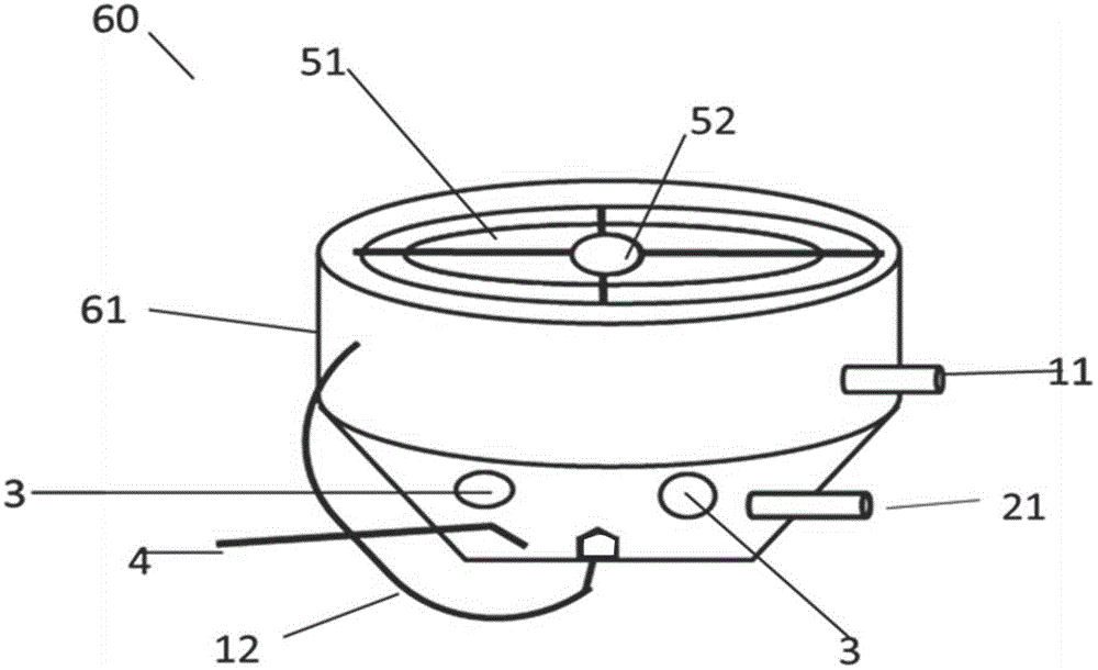
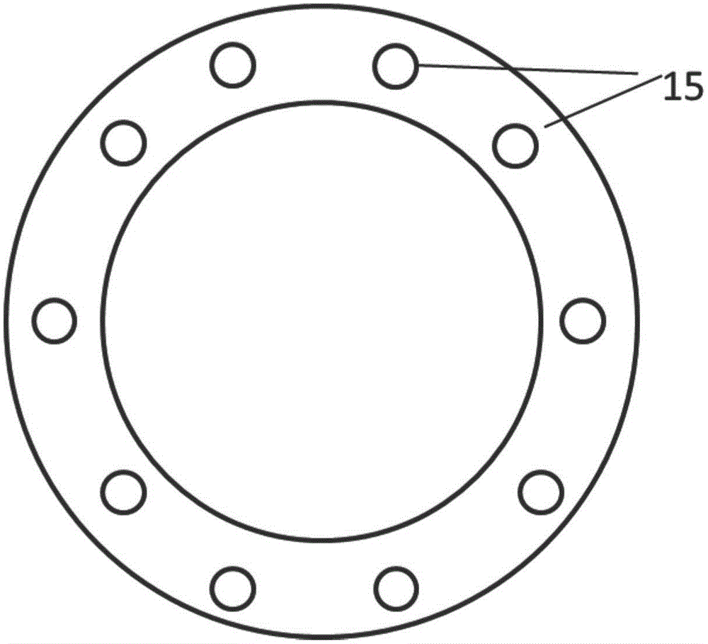
[0020] Such as figure 1 , figure 2 , image 3 , Figure 4 as well as Figure 5 As shown, the burner 60 includes a burner housing 61, a vaporization device 1, a vaporization device inlet pipe 11 connected to the vaporization device 1 and a vaporization device outlet pipe 12; a preheating device 2 and a preheating device 2 Connected preheating device inlet pipe 21; multiple air inlet holes 3, connecting the inner cavity of the burning appliance 60 with the atmosphere; one ignition device 4, the ignition point 41 is facing the liquid outlet of the preheating device inlet pipe 21; one vaporization The nozzle 13 is connected to the gas outlet pipe 12 and is located inside the burner 60; the gasification device 1 is ring-shaped, and its bottom wall 14 is concaved to form 2-18 conical or frustum-shaped bottom wall protrusions 15; the upper half of the side wall of the ...


PUM


Abstract

The invention relates to a liquid fuel vaporization combustion device which comprises a vaporization device (1), a vaporization device liquid inflow pipe (11) and a vaporization device gas outflow pipe (12) which are connected with the vaporization device (1), a preheating device (2), a preheating device liquid inflow pipe (21) connected with the preheating device (2), and a vaporization nozzle (13) connected with the gas outflow pipe (12), wherein the vaporization device (1) is annular, and a bottom wall (14) of the vaporization device (1) is recessed inwards to form 2 to 18 conic or truncated-cone-shaped bottom wall protrusions (15); a circle of liquid inflow groove (16) is fixed to the upper half portion of the side wall of the vaporization device (1) and the position, corresponding to each bottom wall protrusion (15), of the liquid inflow groove (16) is provided with a chute (17); and the gas outflow pipe (12) is connected to the top of one end of the vaporization device (1). By the adoption of the liquid fuel vaporization combustion device, liquid fuel can be completely vaporized and fully burnt, and combustion efficiency is improved.

Description

technical field [0001] The invention relates to a liquid fuel gasification combustion device, which belongs to the field of combustion devices. Background technique [0002] Some existing liquid fuel stoves are prone to incomplete combustion, resulting in carbon deposits, peculiar smells, and black smoke. Liquid fuel stoves mostly use vaporization devices, some of which use vaporization tubes installed at the bottom of the burner, and use the method of opening holes in the burner to let a part of the vaporization gas spray out to burn and heat the vaporization tube, which will affect the intensity of the main flame and reduce the thermal efficiency; some The vaporization tube is installed horizontally on the top of the burner, causing the main firepower to be split into two halves, reducing the thermal efficiency; Chinese Patent Publication No. CN2079290 discloses a liquid fuel furnace (stove) burner, which discloses a tube type vaporization combustion The device is prone t...

Claims


Application Information

Patent Timeline
IPC IPC(8): F24C5/02F23D11/44
Inventor 韩艳玲
Owner XUZHOU LIFANG MECHANICAL & ELECTRICAL EQUIP MFG CO LTD
Learn More