A powder spraying three-pass dryer

A three-pass, dryer technology, applied in the direction of dryers, drying, non-progressive dryers, etc., can solve the problems of not realizing the use effect, not being able to stay for a long time, and the material moisture is not easy to discharge, etc., to achieve effective It is beneficial to the control and flow of heat, improves the quality of drying operation, and has the effect of long residence time

Active Publication Date: 2017-11-21
ANHUI DING BEAM BIO ENERGY TECH DEV CO LTD
View PDF7 Cites 0 Cited by
  • Summary
  • Abstract
  • Description
  • Claims
  • Application Information

AI Technical Summary

Problems solved by technology

[0003] Along with the increasingly higher requirements for production automation and production drying technology and quality, the dryers in the prior art still cannot better meet the corresponding production and drying needs. For example: for the drying of wood powder, one of In the prior art, most of the drying equipment for wood powder in the use process is that the wood powder material is directly in contact with the hot air. Since the hot air contains a large humidity, when the material is mixed with the hot air with high humidity, it will cause The moisture in the material is not easy to discharge; second, in the prior art, the wood powder cannot stay in the equipment for a long time during the operation of the wood powder drying equipment, and the amount of dried wood powder is small, and the equipment is automated during operation. The degree is low, the work efficiency is low, and there are large slag and dust in the dried wood powder. In addition, the drying efficiency of wood powder with high humidity is very low or even the drying operation cannot be realized; thirdly, the current The dryers in the technology generally use single-pass or double-pass drying equipment, which does not achieve the use effect of higher value

Method used


Image

  • A powder spraying three-pass dryer

Examples


Embodiment Construction

[0014] The following will clearly and completely describe the technical solutions in the embodiments of the present invention with reference to the accompanying drawings in the embodiments of the present invention. Obviously, the described embodiments are only some, not all, embodiments of the present invention. Based on the embodiments of the present invention, all other embodiments obtained by persons of ordinary skill in the art without making creative efforts belong to the protection scope of the present invention.

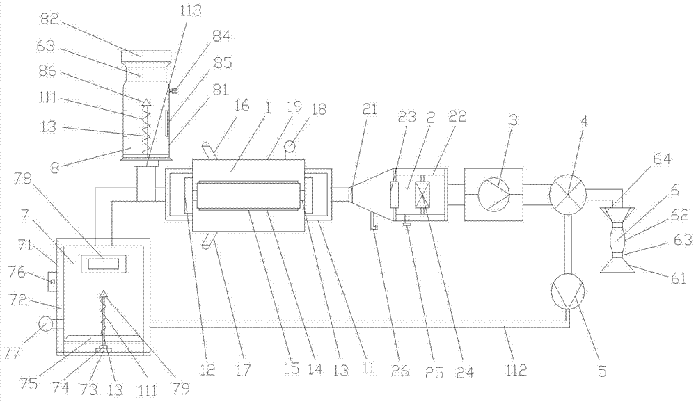
[0015] see figure 1 , a powder-spraying three-pass dryer, which includes a tumble dryer 1, a connector 11 is installed at both ends of the tumble dryer 1, and the conveyer 11 on the left side of the tumble dryer 1 passes through the The pipe 112 communicates with the powder burner 7, and the connector 11 located on the right side of the tumble dryer 1 communicates with the slag remover 2 through the feed pipe 112, and the slag remover 2 is connected with the i...


PUM


Abstract

The invention discloses a powder spraying three-pass drier. The powder spraying three-pass drier comprises a roller drier body. Communicators are installed at the two ends of the roller drier body. The communicator located on the left side of the roller drier body is communicated with a powder burning furnace through a material conveying pipe, and the communicator located on the right side of the roller drier is communicated with a slag separator through a material conveying pipe. The slag separator is communicated with a draught fan through a material conveying pipe. The draught fan is communicated with a dust remover through a material conveying pipe. The dust remover is connected with a dry wood powder collecting device and a powder sending draught fan device respectively through material conveying pipes. The powder sending draught fan device is communicated with the powder burning furnace through a material conveying pipe. The material conveying pipe between the roller drier body and the powder burning furnace is provided with a wet wood powder feeding device communicated with the corresponding material conveying pipe. According to the powder spraying three-pass drier, it is ensured that wood powder can stay in the drier for a long time in the working process, the amount of the wood powder is large, the automation degree is high, slag and dust in the wood powder can be removed, the quality of drying work is improved, meanwhile, the drying work on wet wood powder is achieved, and the three-pass drying efficiency and use value are achieved.

Description

technical field [0001] The invention relates to the technical field of dryer equipment, in particular to a powder-spraying three-pass dryer. Background technique [0002] With the continuous improvement of the level of science and technology, there are more and more types of dryers, and the core technology is becoming more and more mature. Dryers are widely used in many industries such as industry and agriculture. Along with staff and researchers With the efforts of various aspects, the drying equipment technology applied in various industries has also been further improved, bringing a lot of convenience to operators and production automation, and improving production efficiency. [0003] Along with the increasingly higher requirements for production automation and production drying technology and quality, the dryers in the prior art still cannot better meet the corresponding production and drying needs. For example: for the drying of wood powder, one of In the prior art, m...

Claims


Application Information

Patent Timeline
Patent Type & Authority Patents(China)
IPC IPC(8): F26B11/04F26B23/02
CPCF26B11/04F26B23/02
Inventor 梁念喜卢伶俐徐祖成阮景波张波朱华任兆义王家双吴和福宫文伟肖克龙
Owner ANHUI DING BEAM BIO ENERGY TECH DEV CO LTD
Why Eureka
Try Eureka